|
 I See Testers! I See Testers!
|
Revised: 14/3/2019 (Initial Publication: 5/11/2016)
The Big Page of DIY IC Tester Projects
The IC tester is a device of many forms, and with some variety in function. It is however most often content in the role
of indicating whether an integrated circuit is operating correctly, at least to the extent it can determine. It must perform
relatively large parallel I/O operations in order to address all the pins of a chip under scrutiny, and thus often ends up
swelling under the weight of its own chipset. Yet with some careful design, and by offloading tasks of signal generation and
routing to its poor human operator, it can be reduced to just a handful of components.
On this page you will find projects ranging from the incredibly complex to the most painfully simple (painful because the
savings made in design complexity are often at the cost of important automation). With the demand for IC testers perhaps
falling as both IC functions and packages become less accommodating to use in such devices, many of these projects are from
old magazine articles, along with a few complete projects published on the web. This page hopes to show, or link to, all the
information available to the would-be constructor.
Some general notes on IC Tester construction and design selection are printed at the bottom of this page.
The operation of these devices varies considerably in the details, but for ease of selection and comparison, here they are
grouped into a few general categories:
- Passive
- Requires the user to manually configure the test operations, simply providing tools such as output indicators, switches
or patch leads for test stimulus input, and clock generators.
- Comparison
- Compares a suspect IC with another known by the user to be in correct working condition. The user may have to manually
stimulate the inputs as with a standard "passive" tester, with any miss-match between the response of the two identical
ICs detected. Or the tester may instead connect "In-Circuit" to compare a suspect IC in a malfunctioning device to a known
good IC while the device is operating.
- Active
- Automatically presents a stored input combination, specific to the particular IC under test, to the test IC's inputs,
then compares its outputs with those expected from a fully working IC of that model. A microprocessor of some sort is most often
used to load and compare the test data, though such a device must be pre-programmed with the test stimulus data for every
IC likely to be tested.
- PC Controlled Active
- As with active types, the test data is automatically written and read according to programed test data. However the
device is either controlled directly by, or has the option of being connected to, an external personal computer. This
computer can send new test data generated by the user to the tester, thereby allowing the range of supported ICs to be
constantly updated, and avoiding any limit on the number of supported ICs due to the data storage limits of the IC tester
hardware. These devices may be internally controlled by their own microprocessor, or may be operated directly by the PC.
Submissions of any extra information are welcome. Magazine articles, webpages, and any details from personal projects which I
would be happy to host with full attribution on this website.
Email: 
|
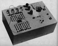
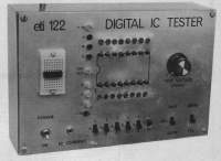
Practical Electronics, Digital IC Tester |
|
| Published | Author | Component Availability | PCB Layout? | ICs Used | ICs in Test Library | Max. Test Pins | Type |
| May, 1971 | D. Burn | 2/4 | No (wiring diagrams) | 1 | N/A | 16 | Passive |
- Tests configured using patch leads and four-pole switches
- Two-speed oscillator, and "toggled" pulse button
- Variable test IC supply voltage 0 - 10V
- IC outputs indicated on four buffered lamps, on when High
|
- Panel meter indicates either test IC supply voltage or current consumption
- Supports RTL, DTL and TTL Logic
- No Pull-up resistors for testing Open Collector outputs
|
|
This manual tester uses a combination of four-pole switches and patch leads in order for its tests to be configured. A
discrete design is used for the oscillator circuit, perhaps in ignorance of the ability of the 7400 IC to be used to form an oscillator
on its own - instead it simply buffers the output as well as handling the "pulse" input which in fact changes the state of a
flip-flop, rather than providing the momentary pulse that is characteristic of other designs. Unlike most, this design sports a panel meter
to report either the current consumed by the test IC (in case the user might determine it excessive), or the regulated output
voltage provided to the test IC, with the different functions selected using a switch. The voltage readout is required as the
voltage supplied to the test IC is variable using a potentiometer in order to cater for the numerous voltage levels at which
different early logic IC families felt most comfortable. The provision of a switch to bypass the voltage control knob and
connect resistors of the required value for a 5V test supply might be an advisable addition now that other voltages are more
rarely required, and their application might have such dire consequences for an innocent IC inserted after an unfortunate knock
against the voltage control knob.
The original design had the constructor, to a large extent, building the four-way switches themselves. Today, four-way slide
switches might be more easily obtained than at the time of the article, indeed perhaps more simply than the rotary switch wafers
required to make the switches to the original design. While talking of substitution, the early 2N2926 transistors used should be
quite adequately substituted by more modern NPN types, perhaps with the common BC549. Otherwise the components used do not
prohibit the construction of this design, and the switches on each test IC pin might avoid the "bird's nest" effect
resulting from the excessive need for patch leads. That said, the suggested (and well illustrated) wiring method, which
includes the use of tag strips, might appear somewhat outdated today.
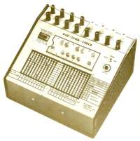
Radio-Electronics, Digi-Dyna-Check |
|
| Published | Author | Component Availability | PCB Layout? | ICs Used | ICs in Test Library | Max. Test Pins | Type |
| May, June 1972 | Jack Cazes | 1/4 | 1xSS supplied, 2 required | 1 (36 transistors) | N/A | 16 | Passive |
- Supports In-Circuit testing
- Uses special ten position slide switches to manually set test configuration
- Oscillator and debounced pushbutton "pulser" to aid manual test configuration
- Outputs for each IC pin displayed on individual lamps, illuminated when High
|
- Designed to allow easy connection of test IC's pins with external test equipment
- No pull-up resistors for Open Collector outputs, but instructions for attaching them when required
- Supports RTL, DTL, TTL and "MOS" Logic
|
|
This particularly early design offers a decent set of features for its age, including in-circuit testing. Unlike other similar
manual testers, it uses a special 10 position, 20 pole matrix switch instead of patch leads. This simplifies construction and
usage, but may leave a modern constructor with a significant difficulty in obtaining equivalent replacements, the original switch
model appearing to have turned into unobtainium.
One PCB layout is provided, but another board is required to complete the project, built in the constructor's method of
choice.
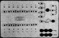
Electronics Australia, Simple Tester for Digital ICs |
|
| Published | Author | Component Availability | PCB Layout? | ICs Used | ICs in Test Library | Max. Test Pins | Type |
| May 1973 | R. K. Laird | 4/4 | No | 3 | N/A | 16 | Passive |
- Basic power supply, oscillator, and manual pulse generator
- Outputs for each IC pin displayed on individual LEDs, illuminated when High
- Counter outputs for additional test signals
|
- IC test configurations set using banana plugs on patch leads
- LED power limited using PWM to prevent overloading IC outputs
|
|
Welcoming the LEDs only just emerging onto the market, this design attaches one to every IC output in this basic manual
tester, while powering them via an oscillator to limit the overall power drawn from the test IC. A 5V power supply suits
testing TTL ICs, while an adjustable oscillator feeds a BCD or Binary counter IC in order to provide a range of test signals
to pipe into the IC under scrutiny. An inverted output is provided for the oscillator, and also for the output of the manual
pulse generator which is constructed, like the oscillators, from the gates of a 7400 NAND IC.
The germanium transistor used in the LED PWM oscillator (Q1) could be substituted for by any number of more modern
equivalents, such as a BC559.
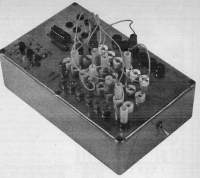
Practical Electronics, Digital IC Tester |
|
| Published | Author | Component Availability | PCB Layout? | ICs Used | ICs in Test Library | Max. Test Pins | Type |
| Sep. 1975 | W. H. Davies | 2/4 | No (Veroboard Layout) | 2 | N/A | 16 | Passive |
- Test stimulus manually configured using patch leads
- High outputs displayed on six LEDs manually connected with IC outputs.
- Constructed using DTL logic ICs
|
- Internal oscillator with selectable frequency and output inversions
- No pull-up resistors for testing Open Collector outputs
- Supports DTL and TTL Logic
|
|
This manual tester provides the basic functions of many later passive testers. Tests, configured using patch leads, have the
option of including the built-in oscillator outputs, which can be configured in a number of arrangements depending on how
the inverted oscillator output is used. The oscillator can be set for two speed settings, slow enough for output changes to
be monitored by the eye.
This design is based around DTL type ICs, some difficulty may be experienced in purchasing these today. a 7404 may be a
pin-compatible replacement for the BP936.
Electronics Today International (Australia), Logic Tester |
|
| Published | Author | Component Availability | PCB Layout? | ICs Used | ICs in Test Library | Max. Test Pins | Type |
| Oct. 1975 | Barry Wilkinson | 4/4 | Yes, 1xSS | 6 | N/A | 16 | Passive |
- Manual pin configuration using patch leads
- Two speed oscillator and six input switches, three of them debounced, to aid manual generation of IC test stimulus
- Output for monitoring test IC current consumption with a milliammeter
- Outputs displayed on individual LEDs for each pin, lit when output High
|
- Tests TTL and CMOS ICs
- No internal pull-up resistors for testing Open-Collector outputs
- CMOS ICs can be tested over their full operational voltage range
|
|
This passive tester design features a good set of basic features and is designed with safeguards against damage of
CMOS ICs (note that earlier CMOS 4000 series logic ICs (as well as the 74C00 series) were more prone to damage by static
discharge than later 4000B types). Test configurations are made using patch leads in a small solderless breadboard mounted on the front of the device, the test
IC is also inserted into this breadboard, and this allows any extra components required for IC testing to be inserted alongside
as required (perhaps some pull-up resistors for those open-Collector outputs, for one thing). Voltages available to the test
IC can be varied between 5V and 15V using a potentiometer, this is for testing CMOS devices over their full voltage range. The
power supply circuit is designed not to damage TTL ICs if they are powered at incorrect voltage due to the user forgetting to
move the provided switch to TTL power mode (5V fixed).
The PCB layout does not provide for mounting the switches and IC test socket on-board. They must be affixed to the front panel
and connected by wires as shown in the provided wiring diagram.
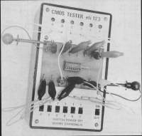
Electronics Today International (Australia), Simple CMOS Tester |
|
| Published | Author | Component Availability | PCB Layout? | ICs Used | ICs in Test Library | Max. Test Pins | Type |
| Nov. 1975 | Barry Wilkinson | 4/4 | Yes, 2xSS | 2 | N/A | 16 | Passive |
- Designed as a simpler alternative design to the "Logic Tester" described in the previous issue of this
publication
- Test configurations set using patch leads with alligator clips
- Internal oscillator to aid manual generation of test stimulus, used in combination with six switched inputs,
not debounced
|
- Outputs shown on six LEDs, lit when High. Manually configured to test IC output pins
- Designed to tests only CMOS ICs
- No internal pull-up resistors for testing Open-Collector outputs
|
|
This otherwise fairly standard low-end passive tester is designed to test only CMOS logic ICs. As a simpler alternative to the
tester described in the previous issue of this publication, it sacrifices many of the more complex features. But it retains the
safety precautions implemented in the earlier design, intended to protect the more easily damaged CMOS logic chips of
the Seventies (before the later 4000B series). The tester may however be able to test many TTL IC families (and later 5V CMOS
logic families), if a 5V regulator is installed to power the circuit (the existing design uses a 9V unregulated supply).
A TTL-only tester design was published in the December 1975 issue, but I do not have a copy of this article.
Practical Wireless, Digital IC Tester |
|
| Published | Author | Component Availability | PCB Layout? | ICs Used | ICs in Test Library | Max. Test Pins | Type |
| Feb. 1977 | W. English | 4/4 | No (wiring diagram) | 1 | N/A | 16 | Passive |
- Uses patch leads to manually set test configurations
- Oscillator, pulser, and other aids to manual test configuration
|
- Outputs displayed on LEDs, though only five provided (four active High, one active Low). Manually configured
to IC outputs on each test
- Can test monostables
|
|
A simple early tester, itself using only one logic IC (a 7400). Some work involved in building the case to suit the sixteen
patch leads used, though plans are provided. A modern constructor may wish to add more LEDs to speed the testing process with
many ICs.
Popular Electronics, Digital IC Tester |
|
| Published | Author | Component Availability | PCB Layout? | ICs Used | ICs in Test Library | Max. Test Pins | Type |
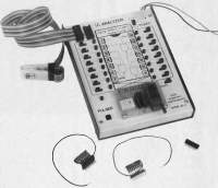
| June 1977 | R. M. Stitt | 3/4 | Yes, 1xSS 1xDS | 11 | N/A | 16 | Comparison |
- Removable "program" PCBs configured either by soldered connections, or configurable patch leads, are used to
set the test sequence for each IC model
- Sixteen LEDs display difference between test and known good IC on any pin. Latched fail LED indicates that a
miss-match has occurred
- Supports DTL and TTL Logic
|
- Oscillator and Seven binary code outputs are available for use in the test stimulus configuration
- Most components still easily available, though the edge connector may be a little difficult
|
|
Certainly the most extensive of the testers from 1977, this design cleverly offers the option of retaining test sequence
programs by using plug-in program boards. This is a considerable time saving feature where different types of ICs are often
tested. However the time and cost involved in making each of the program boards limits the versatility of the system
compared to later computer controlled designs. Instructions for making a customisable program board with patch leads are also
provided.
Radio-Electronics, Digital IC Identifier/Tester |
|
| Published | Author | Component Availability | PCB Layout? | ICs Used | ICs in Test Library | Max. Test Pins | Type |
| June 1977 | Earl R. Savage | 4/4 | No | 0 (16 transistors) | N/A | 16 | Passive |
- Test configurations set using patch leads in empty IC sockets
- Test IC outputs each displayed on LEDs when HIGH
- Supports RTL, DTL, TTL and CMOS logic
|
- Pull-up and Pull-down resistors for testing Open Collector outputs and determining power pins
- Procedure described for identifying unmarked ICs
- Design can be extended to suit ICs with higher pin counts
|
|
A simple design with some facilities for identifying unknown ICs. Does not offer any oscillator, pulse extender or output
latch, but perhaps one of the simplest tester designs, and makes inventive use of IC sockets as patch lead sockets.
Practical Electronics, TTL Tester |
|
| Published | Author | Component Availability | PCB Layout? | ICs Used | ICs in Test Library | Max. Test Pins | Type |
| Nov. 1977 | T. J. Hill | 4/4 | No (Veroboard layout) | 2 | 10+ | 14 | Active |
- An oscillator circuit using the gates from the test IC to flash LEDs in a sequence that reveals their logic
function
- Only tests "quad, two-input" type 7400 Series logic ICs
|
- Separate IC sockets for the two IC pin arrangements that might be expected
- Can test ICs with Open-Collector outputs
|
|
This novel design takes a different approach to testing ICs, tailored for the popular "quad, two-input" logic gate ICs of the
7400 Series. An oscillator feeds one input of each logic gate in the test IC, while the other input is supplied the output
signal from a flip-flop which has divided the frequency of the oscillator output by two. The effect is that the full range of
input combinations are applied to the logic gates, and the number of these that result in a Low output is represented by LEDs
driven by the test IC. The amount of time that the LEDs spend illuminated is determined by the test IC's logic function, and
if it is observed that the LEDs are lit or unlit for more time than expected, the test IC must have a fault.
Two sockets are provided to cater for the indecision of the 7400 series' designers with regard to pinouts. A datasheet
(or the short table in the original article) should be referred to so as to determine the socket in which to insert a suspect
IC. No doubt many more than the ten example ICs listed by the project's author could be tested with this ingeniously simple
circuit, with the corresponding LED on/off time determined in theory beforehand. The only catch, besides the number of 7400 ICs
that are not "quad two-input" being rather hard to overlook, is that there is no way to determine if a tested IC lit the
LEDs with the correct on/off time, but for different logic combinations than intended. A solution to this would be to have
two more LEDs to display the input states, though the oscillator frequency of 2Hz would have to be reduced to allow time for the
user to observe these additional outputs. A debounced push-button to manually clock the inputs and flip-flop in place of the
oscillator would allow for even more time to process the various lights blinking before the operator's weary eyes.
Byte, Programmable IC Tester |
|
| Published | Author | Component Availability | PCB Layout? | ICs Used | ICs in Test Library | Max. Test Pins | Type |
| June 1978 | Mark Thorson | 2/4 | No | 14 | N/A | 16 | Active |
- Automatic testing of ICs after known good IC of same type is automatically "programmed" into RAM
- Tests most SSI and MSI TTL ICs
|
- Eight counter outputs, one clock output, and six inputs, to be manually configured with test IC inputs and
outputs
|
|
This ingenious design allows complete functional tests of both basic logic gates and more complex ICs such as counters and
shift registers, without requiring a microprocessor. Test outputs are generated by a counter that also controls a series of
RAM ICs, which can either store the outputs of a known good IC, or compare a suspect IC against the results from a good IC
already programmed in.
Similar in concept to later micoprocessor-controlled designs, this tester cleverly works with the technology economically
available to constructors at the time. However compared to later programmable testers, one key limitation is that only one
test program can be kept in RAM at a time, so known good ICs must be kept handy to use for automatic programming before every
test. Also the inputs and outputs are limited and aren't automatically configured, so patch leads are still required to
manually configure the tester to each test IC model.
The circuit uses standard 7400 series logic ICs, including 74S200 256bit RAM ICs. However a range of other RAM ICs are
listed as alternatives, and this may be handy for modern constructors looking for these obscure parts. Later models of RAM
ICs with multiple data bits may be a convenient option to reduce the chip count while requiring minimal modification
to the circuit.
Practical Electronics, Chip Checker |
|
| Published | Author | Component Availability | PCB Layout? | ICs Used | ICs in Test Library | Max. Test Pins | Type |
| Apr. 1980 | L. V. Cooper | 2/4 | Yes, 1xSS | 14 | N/A | 16 | Passive |
- Inputs manually pulled up/down via 3-position switches on each pin
- Detects inadmissible logic levels and open-circuit test pins, as well as logic High and logic Low levels
- Input states displayed on individual 7-Segment displays
|
- Can test ICs with Open-Collector outputs
- Designed to test TTL and DTL logic, could test CMOS as well
- Optional manual pulse generator for testing ICs with clock inputs
|
|
This is the most advanced of the passive IC tester designs that I've seen. While most use dedicated level detection
circuits on each input, this circuit can boast a multiplexing system that allows just one set of comparators to be used. As
well as the standard logic level indication, this has also allowed for open-circuit inputs, and inadmissible voltage levels in
the "intermediate zone" between High and Low, to be detected practically.
Four 4016/4066 analogue switch ICs are controlled by a 4514 line decoder IC to select each input individually and pass it
for assessment by the three comparators. The outputs from these are manipulated by a logic network to suit the taste of a 4511
7-segment display driver that drives the parallel-connected segments of the LED displays. Three 75492 LED driver ICs (now
rather obscure) select the active display section to match the pin being checked, and they are scanned at 500Hz so the status
of every pin is visible at once to the eye.
The comparators are manually adjusted for the the High and Low voltage thresholds, so although the tester is designed for
use with TTL logic, I think a switch could be installed to swap between trimpots and allow CMOS levels to be set as well.
Open-circuit inputs are detected by maintaining a negative voltage on each input pin, supplied via a 1Mohm resistor with
the voltage limited by germanium diodes to no more than about -0.2V in order to protect connected ICs. When an IC input or
output is connected to the pin, it pulls up the negative voltage and thereby reveals its presence to the comparator circuit.
Apparently CMOS inputs are too stealthy for this method of detection, so they will appear as open-circuit.
Electronics Today International (Australia), CMOS Tester |
|
| Published | Author | Component Availability | PCB Layout? | ICs Used | ICs in Test Library | Max. Test Pins | Type |
| 1981 | C. Jordan | 4/4 | No | 0 | 7 | 14 | Active |
- An oscillator circuit using the gates from the test IC to flash LEDs and optionally output to earphone
- Can not test ICs that don't work in an oscillator configuration
|
- Tests: 4001, 4011, 4030, 4071, 4077, 4081, 4093
|
|
This is a basic circuit submitted by a reader of the publication and printed in their third book of circuits notes "ETI
Circuits No 3", it may have been printed in the magazine itself before this. It uses the gates of the test IC to form two
oscillators using a common circuit, then buffers the output with two transistors (which could be substituted with most NPN
low power transistors if required) so that it can drive two LEDs and an earphone if desired (presumably for basic identification
of the operating frequency). If the LEDs flash, or you hear the right sound in your ear, the IC's OK. Two frequencies are
selectable using a switch.
Electronics Today International (Australia), CMOS Gate Identifier |
|
| Published | Author | Component Availability | PCB Layout? | ICs Used | ICs in Test Library | Max. Test Pins | Type |
| 1981 | Unknown | 4/4 | No | 0 | ? | 14 | Active |
- Identifies CMOS quad, dual input AND, OR, NAND and NOR ICs
- Tests the function of all gates, but only with one input configuration (failures may be missed)
|
- Output displayed on a single 7-segment + decimal point LED display segment
- Can not test ICs with other functions, or with unconventional pin-outs
|
|
This "identifier" very cleverly uses just three transistors, four resistors, and a single 7-segement LED display to identify,
and to some extent test, quad AND, OR, NAND, and NOR gates, with dual, inputs from the 4000 series of CMOS logic ICs. Using an inventive arrangement
of the test IC's inputs and outputs, it controls the display such that "A" is lit when an AND or NAND gate is inserted, while
an "O" indicates an OR or NOR. The decimal point indicates the inversion, so if it is lit the IC is either NAND or NOR. Other
common models of low power NPN transistor could be substituted for the three BC109s if required.
The design isn't ideal for testing ICs, because although it will detect failures that stop the IC working in the input
and output configuration used, the IC could fail to work in other configurations that it can't test.
Some success may also be had in using this tester with 7400 series ICs, where the pin-outs match those commonly used in the
4000 series (eg. 7400 quad NAND has the same pinout as the 4011, but the 7401 doesn't). There should be a 1K resistor between
pin 1 of the test IC and PB1, for use with Std. TTL type 7400 series ICs which shouldn't have their inputs directly connected
to the supply voltage (other TTL families such as 74LS00 don't have this restriction). For the 7400 series, the voltage should
also be under 5.5V, not the 6V in the schematic. The design won't work with Open-Collector ICs.
Radio-Electronics, Programma III |
|
| Published | Author | Component Availability | PCB Layout? | ICs Used | ICs in Test Library | Max. Test Pins | Type |
| Jan. Feb. Mar. 1983 | Gary McClellan | 3/4 | Yes 1xSS 1xDS | 7 | N/A | 16 | Passive |
- Test configurations set using 3.5mm audio plugs (without leads, and with contacts shorted) inserted in sockets
- Tri-colour LEDs display pin status for each pin of test IC (neatly done in the circuit)
- Supports TTL and CMOS logic
|
- No oscillator, but manual pulser and test IC power overload detection
- External circuits can be connected via programming plugs
- Open collector outputs not supported, unless programming plugs with internal pull-up resistors were used
|
|
A neat design with an inventive alternative to patch leads for test program configuration. Doesn't offer all the features
of other passive testers, but does make it easy to connect external test equipment to generate extra test signals. Also
includes a circuit to detect if the test IC is drawing too much power due to an internal short.
Radio-Electronics, Computer Controlled IC Tester |
|
| Published | Author | Component Availability | PCB Layout? | ICs Used | ICs in Test Library | Max. Test Pins | Type |
| Sep. Oct. Nov. 1984 | Floyd L. Oats | 4/4 | No | 10 | Not Supplied | 16 | PC Controlled Active |
- Original design for S-100 computers, but adaptable to other 8bit and 16bit computers (an old 32bit PC with
ISA card sockets might manage it as well)
- Software not provided, instructions provided to assist constructors in writing their own
- Manual input switching required before tests using DIP switches
|
- Design does not allow testing of ICs with Open-Collector outputs
- Add-on device described to allow this to be used with an Oscilloscope as a 16 channel Logic Analyser (4 extra ICs
required)
- Another add-on device described to allow the tester to be used as an EPROM Programmer
|
|
Unusually this is more of an outline than a complete project. It describes the electrical connections for the IC test
circuitry, and the method of accessing it using the computer, but it leaves the constructor to design the specifics of the
bus interface, and to write the software to operate the device. This is to allow it to be constructed to suit whichever of
the many computer architectures may have been in use by the reader in the mid 1980s (these days one would of course assume the
PC as the target platform).
The end of the second part describes modifing the tester for use as a logic analyser in combination with an oscilloscope.
The third part concerns modifications that allow the tester to be turned into an EPROM programmer, capable of programming
some early EPROMs (2704, 2708, 2716, 2732, 2758).
Radio-Electronics, IC Tester |
|
| Published | Author | Component Availability | PCB Layout? | ICs Used | ICs in Test Library | Max. Test Pins | Type |
| Sep. Oct. 1985 | David H. Dage | 3/4 | Yes, 1xSS 1xDS | 11 (20 Transistors) | N/A | 16 | Comparison |
- Allows In-Circuit comparison with known good IC while the circuit operates, or manual test stimulus using
switches (in or out of circuit)
- Individual LEDs for each pin indicate any mis-match between the outputs of the test IC, and the known good
comparison IC. Indications can be latched or automatically extended in duration to make them more visible
in fast circuits
- Able to be powered by the device under test when used In-Circuit (5-15V operation range)
|
- Pulse generator can momentarily toggle the logic level of a pin in an active circuit without causing
damage to the output drivers which it overrides
- Oscillator available for use with manual test configuration
- Tests TTL and CMOS logic
|
|
This device is perhaps best suited to work in troubleshooting circuits where a faulty IC is suspected of causing trouble, or
indeed just to view signals being sent and received by a particular IC. The pulse generator is also a useful aid to in-circuit
work, as it allows the user to experiment with potential causes of malfunction. In addition, the device offers the
functionality of normal stand-alone IC testers by allowing the user to apply input signals manually using the individual slide
switches provided for each IC pin.
Hands-On Electronics, Digi-lyzer IC Tester |
|
| Published | Author | Component Availability | PCB Layout? | ICs Used | ICs in Test Library | Max. Test Pins | Type |
| Aug. 1987 | W. Schopp | 4/4 | Yes, 1xSS | 6 | N/A | 16 | Passive |
- Manual stimulus using push buttons to pull pins high. No pulse generator, oscillator, debouncing etc.
- Two ZIF IC sockets on board, but does not offer comparison testing. For some reason the designer has provided
separate sockets for 14pin and 16pin ICs.
- Individual LEDs indicate the High/Low status of each pin.
|
- Test voltages selectable to suit either 5V TTL or to test the higher voltage capability of CMOS ICs
- Allows for a limited number of common ground and power pin configurations for the test IC
- No pull-up resistors on pins for testing Open-Collector outputs
|
|
This passive tester is notable for containing two ZIF IC sockets, but only using one at a time, with separate sockets
provided for testing 14pin and 16pin ICs. The need for this segregation is unclear, as other testers generally have the user
place smaller ICs in the sockets of their taller cousins. It is perhaps just to extend the selection of power supply pin
configurations, a job to which eleven slide switch are already dedicated.
Few features are provided to the user to aid in generating test stimulus. Oscillators, pulse generators etc. are dispensed
with in preference to the tenacity of the operator's button-pressing digits. However the design does allow a higher 12V
supply voltage to be applied to CMOS ICs in order to test them in the higher range of their voltage tolerance.
Electronics Today International (Australia), In-Circuit Digital IC Tester |
|
| Published | Author | Component Availability | PCB Layout? | ICs Used | ICs in Test Library | Max. Test Pins | Type |
| Aug. 1987 | All Electronic Components | 4/4 | Yes, not provided | 0 | N/A | 24 | Passive |
- Shows pin status of IC operating In-Circuit. Nothing else.
- Individual LEDs directly powered by each pin are illuminated when their pin is brought High
- Can test ICs operating in circuits with supply voltage between 5V and 22V
|
- Test IC connected using an IC test clip
- Ground connection made to test circuit using a clip lead
|
|
This extremely basic design hardly deserves the grandeur of the title given to it by this publication. In reality it simply
connects to an IC operating in a circuit and uses the High levels that appear on its pins to light corresponding LEDs, grounded
by a 1K2 resistor which connects back to the circuit using a clip lead. The user views the changing states of the inputs and
outputs on the relevant LEDs (or quite possibly the whole lot of them glowing, if the circuit is running too fast for the eye
to see), and consults the datasheet for the particular IC model to determine whether it is playing by the rules.
In cases where the output of an IC is already significantly loaded by the circuit it is operating in, adding the extra load
of the directly powered LED may be enough to induce a malfunction itself. In other circuits however it may be useful, particularly
where the user has designed the circuit and is fully aware of the load conditions of the connected IC. Indeed it may be a fault
in a newly born circuit design that the user is trying to detect, rather than the fault in the IC itself.
Note that some other, more genuine, IC testers, also allow In-Circuit logic states to be viewed. Many have buffered
inputs so the concern of the LEDs overloading some outputs in a circuit is greatly reduced (there's only the input loading from
the buffer IC to keep you nervous). In many cases this functionality is referred to by the similarly exuberant title of "Logic
Analyser".
Byte, Circuit Cellar IC Tester |
|
| Published | Author | Component Availability | PCB Layout? | ICs Used | ICs in Test Library | Max. Test Pins | Type |
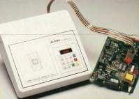
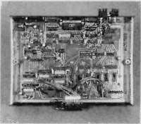
| Nov. Dec. 1987 | Steve Ciarcia | 2/4 | No? | 16 | Over 600! | 24 | PC Controlled Active |
- Stand-alone active IC tester based on Intel 8031 microcontroller, which can also connect to an external computer
via an RS-232 interface for easier operation and increased test data storage.
- Includes optional LCD display to show test results in stand-alone operation
- Tests IC outputs under load condition, and allows testing of Open-Collector and Tri-State outputs
|
- By far the most complete library of test routines available, all of which can be stored in the EPROM memory
for stand-alone operation
- Allows power connections to the most common power pin locations on logic ICs, though not all possible
combinations
- Supports TTL and CMOS ICs
|
|
While not offering the In-Circuit functionality of the simultaneously published project below, this design offers a very
well considered set of testing capabilities. The article itself describes the process of these considerations quite well, and
as such is recommended for reading even, for those not looking to build this particular design.
An integrated, optional, LCD display allows stand-alone operation whereupon IC type is determined automatically by the
tester, while "terminal" and "PC-Host" modes both allow methods for control by
an external computer. The Outputs of the test IC are subjected to brief loading to better assess their condition, and power
is applied automatically to the relevant IC pins by transistors (however only a limited number of power pin configurations
are supported). The microcontroller used may have to be acquired as New Old Stock because Intel no longer manufacture the original
8031 (it may be easy to adapt the design to use the compatible 8051 IC), however the other components used should still be
quite easily sourced. A printed circuit board is shown in the images, however I have been unable to find the layout for making
it, so I am not sure whether it was published (do tell, if you know where to find it).
In part two, the author notes that the IC test library supports around 800 ICs, an increase over the 600 claimed in part one.
I've used the lesser figure in the table because it's far above the claimed numbers from any other tester here anyway. About
200 of these tests are said to be unique, with the numbers supported increasing once the various IC models with duplicate
functionality are considered.
Perhaps the best feature of this IC tester is the extensive range of ICs for which test routines have been compiled. Luckily
the test data files as well as the EPROM image and PC software are still to be found online, and links to them follow.
Radio-Electronics, In-Circuit Digital IC Tester |
|
| Published | Author | Component Availability | PCB Layout? | ICs Used | ICs in Test Library | Max. Test Pins | Type |
| Nov. Dec. 1987, Jan. 1988 | Bill Green | 1/4 | Yes, 2xDS | 15 | Unknown | 24 | PC Controlled Active |
- Microprocessor controlled using Z80 CPU
- Can internally store up to 105 test data sets for different ICs
- Can communicate with an external computer using RS-232, allowing new test data to be generated and stored
externally, then uploaded (or downloaded) as required
- IC type selection and test data entry without external computer can be achieved using the built-in keypad and
LCD display
- No pull-up resistors for testing Open Collector ICs
|
- Allows In-Circuit testing by pulling pins briefly to the required test logic levels without causing
damage to the output drivers which it overrides
- Design relies on three custom manufactured logic ICs which are naturally no longer available, hence the design
can not be built using parts available today without modification
- Supports TTL and CMOS Logic
- Ground connection to the tested circuit, and power connection to supply pin of ICs tested out of circuit, must
be applied manually using clip leads with IC pin clips.
|
|
This active tester distinguishes itself from the previous In-Circuit tester described in the same publication by offering
microprocessor control, and with it the ability to automatically store and execute pre-programed IC test routines. Using a
standard RS-232 interface, it can also communicate with a personal computer to further expand the convenience of its operation.
One of the most unique aspects of this magazine project is that it includes in its construction three ICs which were custom
manufactured to suit its requirements. Unfortunately while this may have been useful in reducing the part count at the time,
it means that the modern-day constructor will have almost no hope of building the design without some modification to account
for the unavailability of these unique chips.
Either by coincidence or as a sign or competition, this design was published at the same time as the Circuit Cellar
IC tester above, which shared similar features. In comparison, this design does not test the IC outputs under load or facilitate
testing ICs with Open Collector or Tri-State Outputs. However before you rush to judgement, it does include a more comprehensive
method of stand-alone operation including the ability to program new IC test routines without connecting a PC, and of course
the In-Circuit testing functionality to which it is named.
Note that although I've listed this as a "PC Controlled Active" type, the externally connected computer appears
limited to the roles of helping users generate test data more easily than by the paper and pencil method also described, and
shuffling the resultant test datasets back and forth between the two devices. The PC is not able to initialise a test, or
view its results.
Radio-Electronics, Commodore 64 Digital IC Tester |
|
| Published | Author | Component Availability | PCB Layout? | ICs Used | ICs in Test Library | Max. Test Pins | Type |
| May 1988 | Jim Barbarello | 2/4 | No | 1 | Unknown | 16 | PC Controlled Active |
- Connects to the Expansion Port (Cartridge Port) of the Commodore 64 computer and requires no external power
- Manual power pin configuration using patch leads inserted in IC sockets
- Article includes BASIC listing for simplified software without test data library support
|
- Tests TTL and CMOS logic, as well as Transistors and Diodes
- No pull-up resistors for testing Open-Collector outputs
|
|
This is the simplest computer controlled tester design I know of, consisting almost entirely of a 6821 parallel interface IC
and three IC sockets, one for the test IC and two for manual power pin configuration. Despite its simplicity, the tester is
able to perform full truth table tests of up to 100 input configurations for each IC type. Unfortunately the program listing
supplied does not support storing the IC test data once entered. Software with this facility was available at the time, along with
a set of premade libraries, for purchase on floppy disk.
Although the only IC required, the modern constructor will be forced to find a 6821 for sale as New Old Stock because it is
no longer manufactured. Today of course the Commodore 64 computer it is designed to work with will also be a challenge to
acquire, unless you are crazy enough to already collect such machines, like I am. However if these prerequisites can be obtained,
this design certainly makes a clear distinction for itself as an easy solution for basic automatic IC testing.
Radio-Electronics, In-Circuit Digital IC Tester |
|
| Published | Author | Component Availability | PCB Layout? | ICs Used | ICs in Test Library | Max. Test Pins | Type |
| Sep. 1988 | Bill Green | 1/4 | Yes, x1 | 4 | N/A | 20 | Comparison |
- Can only be used In-Circuit - provides no means for manual stimulus of the test IC
- LEDs for each pin light to show any difference between test and known good IC. Can be latched for use with fast
circuits
- Procedure described for usage as a basic "logic analyser"
|
- Design relies on four custom manufactured logic ICs which are naturally no longer available, hence the design
can not be built using parts available today without modification
|
|
Notably designed by the author of the previous In-Circuit IC Tester project from Radio-Electronics, this design is a vastly
simplified approach, but one which relies even more heavily on custom manufactured ICs for its construction. Unlike other
"comparison" type designs, this tester does not offer any way to stimulate the inputs of the IC under test. This means that
the circuit that the test IC is part of during an In-Circuit test must provide all the input signals to trigger the outputs
compared with the known good IC inserted in the IC tester. For this reason tester cannot test ICs out of circuit.
Radio-Electronics, "PcIC" PC-Based IC Tester |
|
| Published | Author | Component Availability | PCB Layout? | ICs Used | ICs in Test Library | Max. Test Pins | Type |
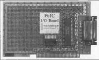
| July 1991 | James J. Barbarello | 2/4 | No | 2 | Unknown | 16 | PC Controlled Active |
- Connects to an IBM PC or clone as an 8bit ISA card
- Manual I/O routing for the pins of the test IC is required due to the limited parallel I/O available from
the 8255 interface IC used. This is achieved using a breadboard and instruction to the user from the computer
software
|
- Can test TTL and CMOS ICs. Manually placed pull-up resistors would be required to be inserted in the signal
routing breadboard in order to test ICs with open collector outputs.
- Original PC software not available. Was sold on floppy disks for $10 at the time of publication.
|
|
This is among the simplest of the computer controlled IC testers, but as with most of the simplified designs it offloads more
of the configuration work to the user. Two modified solderless breadboards (one containing the ZIF socket for the test IC)
are connected from outside the computer using a ribbon cable with a DB25 connector. The software instructs the user how to
arrange jumper wires to route inputs and outputs of the IC tester to their required positions on the IC, this arrangement
changes with each different model of IC tested.
The IC tester is built on an ISA prototyping board. This, and the 8255 parallel interface IC, may prove slightly difficult
to acquire today for a reasonable cost (although this company, Futurlec, happen to still
stock both) .
Electronics Now! (Radio-Electronics), T1004 Digital Logic IC Tester and Identifier |
|
| Published | Author | Component Availability | PCB Layout? | ICs Used | ICs in Test Library | Max. Test Pins | Type |
| June, Oct. 1992 | Steve Wolf | 2/4 | Yes, 2xDS | 46 (13 for interface board) | Unknown | 24 | PC Controlled Active |
- Connects to IBM PC or clone using custom interface card (also compatible with other devices described in the
series), described in the June issue.
- Tests input trigger levels, hysteresis, and output instability under load, as well as the usual truth table
testing.
- Detection of Open-Collector outputs, and even gate type identification (Std. TTL, LS, HCT etc.)
- Automated identification of unmarked ICs.
|
- Tests TTL and CMOS ICs
- Only supports ICs with "standard" power and ground pin locations!? (a surprising omission from an otherwise
amazing features list).
- PC software was available from Radio Electronics' BBS as a self-extracting archive named "T1004.EXE". I haven't
been able to find a copy still online.
|
|
This is by far the most advanced DIY IC tester project that I have discovered so far. It contains features unconsidered in even
the most complex of the other testers. This shows in the complexity of the circuitry, and the component cost of its
construction. Certainly if you want the best guarantee available from a DIY device that your logic IC is working correctly,
this will give it to you. If you're just looking for a challenging project to sink your teeth into this might fit the bill as
well. However overall the increased complexity isn't really justified for a device intended just for general use.
This project is part of a series of test equipment which connects with an IBM PC using a DIY interface card connected to
the ISA bus. This custom parallel interface was required due to the limitations of the original PC parallel port. However the
parallel port design was enhanced after this project was published to support the bi-directional communication that it
required. As a result, a redesign could remove the need for a custom interface card. Of course today a USB interface, and
the necessary microcontroller, may be more practical. However the techniques used in this design may still prove worthwhile as
the basis for a modern "ultimate DIY IC tester".
CirKit Electronics Catalogue, Logic Chiptester |
|
| Published | Author | Component Availability | PCB Layout? | ICs Used | ICs in Test Library | Max. Test Pins | Type |
| 1994 | Paul Stenning | 3/4 | Yes (inc. Gerber files) | 19 | 76 (138 with DSA software) | 24 | PC Controlled Active |
- Connects to PC via Serial port
- Common power pin configurations selected with a rotary switch, manual configuration of other power pin locations
(except for ICs with more than 20 pins)
- Includes pull-up resistors for testing ICs with Open Collector outputs
|
- Full DOS software and circuit board layouts available online
- Software for DSA IC tester below is compatible (supports identifying unknown ICs)
|
|
Although afflicted with a much higher chip count than some other PC controlled testers with similar feature sets, this design
offers good compatibility with the standard range of logic ICs available, in return for the tireless soldering of its
constructor. By inserting wires into the IC socket to connect power to ICs with unusual power pin locations, the user is able
to test those nonconformist ICs which can't be satisfied with the standard power pin positions selected by a rotary switch. Note
that this would be difficult if a ZIF type socket was not used for the test IC (and it's a little tricky in any case).
The project's author has kindly made a comprehensive collection of information available for this design in a ZIP file on
his website. This includes Gerber PCB design files which may be used to have a PCB professionally made with plated
through-holes to significantly ease the burden of constructing the board, with it's numerous under-IC pin connections and
VIAs (If you have any spares afterwards, donations are welcome!). Despite this unusual wealth of information for an old magazine
article, some trouble may still be had today in finding the Harris 6402 serial UART IC used, at least for a reasonable price.
Electronics Now! (R-E), "Chip Tester" |
|
| Published | Author | Component Availability | PCB Layout? | ICs Used | ICs in Test Library | Max. Test Pins | Type |
| Jan 1995 | Mark Hanslip | 4/4 | No | 5 (for max 16 pins) | N/A | Chosen by Constructor | Comparison |
- Can only be used In-Circuit - provides no means for manual stimulus of the test IC
- Unlatched LED on each test IC pin indicates miss-match of signals between test and reference IC. A latched
"failure" LED indicates that a miss-match has been detected.
|
|
|
This IC tester is very similar to the second of Bill Green's designs, published in the Radio-Electronics Sep. 1988. The main
advantage of this design to the modern constructor is that it does not rely on any custom manufactured ICs. Like the earlier
design, it relies on the device that the test IC is operating in to provide the input stimulus. Unlike that design, it does
not latch the miss-match indicators on each pin, only on an overall failure LED. Therefore the user will have to be sharp
eyed to catch sight of which pin/s triggered the failure indication.
The design is such that the constructor can extend it to whatever maximum number of pins they want their tester to be able
to test. This determines the number of ICs required to construct the device. In addition to the 7400 IC required for the latch
circuit, one 74LS266 IC is required for every four IC pins able to be tested.
Elektor Electronics, Intelligent IC Tester |
|
| Published | Author | Component Availability | PCB Layout? | ICs Used | ICs in Test Library | Max. Test Pins | Type |
| Jan. Mar. Apr. 1998 | Laurent Lamesch | 2/4 | Yes, 1xDS, 1xSS | 10 | 327 | 24 | PC Controlled Active |
- Automatic power pin configuration to common pin locations
- LCD + Keypad Interface allows independent operation
- Programmable pull-up resistors and high impedance state detection for testing ICs with Open-Collector and
3-State outputs
|
- Uses 80C535 microcontroller (8051 derivative)
- Connects to PC via RS232, software available for DOS
- Identifies unmarked ICs
- Monitors test IC current consumption
- Tests TTL and CMOS logic
|
|
Winner of a project design competition held by the magazine, this IC tester was presented in full after being summarised
as part of the "supplement" originally covering the contest. It is a complex design placing usual emphasis on
detection of the high impedance state with ICs incorporating three-state outputs.
Power pin configurations are switched automatically by transistors, with a separate voltage regulator which is adjusted
so that the output is high enough to overcome the voltage drop over the switching transistors. This second regulator is also
watched over by the microcontroller, which can read its output current and thereby display the test IC's current consumption
to the user.
Read and write functions to the 24 pin test socket are acheived using two Z80PIO ICs, chosen because all of their I/O
lines can be individually programmed to work as inputs or outputs. The impressively large test set is stored (along with
the microcontroller firmware) on an EPROM, which is addressed via a GAL that must also be custom-programmed.
The device is designed to operate primarily as a stand-alone unit, with PC software intended mainly for developing and
testing sequences for additional ICs before reprogramming the EPROM with these new tests included. While ICs can be
tested, and the results analysed, using the PC software, the article notes that it can take ten minutes or more to test
some ICs this way.
The main PCB is very tightly packed and uses some surface-mount components. Unfortunately the design makes it virtually
impossible to contruct if the PCB doesn't have plated through-holes, which rules out common DIY PCB manufacture processes.
Nevertheless the PCB designs are printed in the article. The software for the EPROM, GAL and PC was sold on floppy disk or CD,
and included the original source code. The CD also included the PCB layouts which might be suitable for submitting for
professional manufacture. These resources don't appear to be available on the current Elektor website, but it could be worth
contacting the magazine to request them.
The microcontroller at the heart of this design is the 80C535, a derivative of the 8051 with expanded I/O and a built-in
Analogue to Digital Converter. This, and its close equivalents, seem to have gone out of production. However they may still be
available as New Old Stock from some suppliers, and in particular there are quite a few on Ebay at the time of writing (2018),
albeit for a significant price.
DSA IC Tester |
|
| Published | Author | Component Availability | PCB Layout? | ICs Used | ICs in Test Library | Max. Test Pins | Type |
| Oct. 15, 2000 | David Setya Atmaja | 3/4 | Yes, 1xDS | 15 | 138 | 24 | PC Controlled Active |
- Connects to PC via Bi-Directional Parallel Port
- Software available for DOS, with good number of ICs provided in test library
- Based on the CirKit Catalogue IC tester designed by Paul Stenning (above), software is backwards compatible with
this earlier design.
- Relays automatically switch common power pin configurations. Patch leads used for non-standard power pin locations
on ICs with less than 22 pins.
|
- Includes pull-up resistors for testing ICs with Open-Collector outputs
- Experimental support for identification of unmarked ICs (slow, but it seems to work fairly well)
- Tests TTL and CMOS logic
|
|
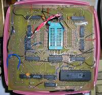
This was the first of the two IC testers here that I actually built, so for once I actually have some idea what I'm talking
about when I describe it. Being a numerically orientated sort, I was most attracted by the relatively large number if ICs in the
provided test library (I hadn't yet discovered the Circuit Cellar IC tester and the truth table encyclopaedia it comes bundled
with). This feature is however less indicative of the design of the tester itself, as of it's designer's stamina, but nevertheless
the hardware served up is quite sound.
Based on the previously mentioned CirKit Catalogue IC tester designed by Paul Stenning, the main difference is that this
design is connected to a PC on the parallel port, rather than by serial RS-232. To this end the obsolete Harris 6402 serial interface
IC from Stenning's design is replaced with an 8255 Parallel interface IC, the availability of which has also now fallen away,
such is life. Anyway assuming you can get your hands on an 8255 (and it might not be all that hard really), you will find
that this tester offers another feature over its ancestor, automatic switching of the power connections to the test IC. Yes a
bank of five little relays clatter away, saving your fingers from fumbling the rotary switch of the old design. Actually I
decided that I wasn't posh enough for this and installed switches anyway, but there's just no helping some people. Unconventional
power pinnings are again catered for by sticking wires into the ZIF socket, just like Stenning would have you do.
The software is based also on it's CirKit ancestor, but rewritten and given what can be modestly described as a colourful
presentation. Things flash, things beep, but let's face it, after sitting down and plugging half a tub of possibly iffy ICs
sequentially into the test socket, you need all the audio/visual stimulation you can get. There's a separate PDF user guide for
the software on the project page as well, the English in this, and the other, documentation is well... interpretational, just to
warn those of you who are particularly reliant on grammatical structure.
Look at my notes for some more specific comments, and a few extra IC test files that I've managed to punch in.
Everyday Practical Electronics, Digital I.C. Tester |
|
| Published | Author | Component Availability | PCB Layout? | ICs Used | ICs in Test Library | Max. Test Pins | Type |
| Oct. 2002 | Joe Farr | 3/4 | Yes, 1xSS | 2 | 89 (inc. those in alt. s/w) | 24 | PC Controlled Active |
- Based around PIC16F877-20P microcontroller
- Connects to PC via Serial Port
- Manual DIP switches for selecting common power pin configurations, and patch leads plus sockets for non-standard
configurations
- Pull-up resistors for Open-Collector outputs
- Software for PIC and PC still available from the EPE FTP site
|
- PC software with full graphical interface available for Windows 95 through XP (unknown if it works with later
Windows). Alternative software now available for Linux and Windows.
- Original software includes the ability to use the tester as a 24 channel logic analyser
- Alternative software includes IC identification, ROM reading and data verification, as well as SRAM IC testing
- Tests TTL and CMOS logic
|
|
This appears as a very attractive design for the modern DIY constructor for a number of reasons beginning with it's relative
simplicity in using just two ICs. Unlike some earlier low part count testers, this design is not limited in the scope of its
test abilities, or overly demanding of its user for manual configuration. Four DIP switches are used to select power pin
configurations (with room left for another four, to indulge the constructor's own visions of power), while unusual pin locations
are catered for in the usual patch lead method, with pin socket strips running along either side of the ZIF test socket to allow
the + and - wires to be pushed in where required. Power pin switching/wiring is described by the PC software, which features
a full Windows GUI (as opposed to the DOS command line and text-mode interfaces of many other projects (the option of a command
line interface is offered by the alternative software, which also has a GUI)).
The project is designed for construction with two types of resistor module in DIL (same package as ICs) and SIL packages. These
may be more difficult to obtain than standard resistors from your preferred components supplier (or parts box), but can be
substituted for standard resistors connected in the equivalent electrical configuration as shown in the schematic. On a similar
note, the PIC16F877-20P microcontroller at the heart of this project has since fallen somewhat out of favour, although should
still not be terribly hard to obtain. The webpage for the alternative PC software linked to below has some short construction
notes for this tester, including a description of programming the PIC using a Willem EPROM Programmer.
While the hardware of this project is not particularly more capable than many other PC controlled testers, the software
developed for it has allowed a range of extra functionality not matched by any of the other designs I've seen. The original
software features a Logic Analyser display which shows the pin status of the IC during tests, and can also be used to monitor
external circuits with some very basic additional abilities such as triggering on a set pattern. The accuracy of the logic
display is limited by the hardware, which samples the pins at slightly different times during a cycle.
The alternative software made recently available by another individual supports Linux and later Windows, while also adding
a number of extra features to the tester (though it does not include the Logic Analyser functionality). ROM reading and
verification is particularly useful for testing the integrity of data on EPROMs, while the SRAM test further extends the tester's
abilities to yet another type of IC. It also offers the more common ability to identify ICs of an unknown type, although the
design of the tester limits the safety of this function due to the low value current limiting resistors used (in many cases it
will probably work fine, though there may be issues if the tester pauses or freezes during a test).
The IC test libraries are compatible between the two programs, so be sure to grab the files from both, whichever one you choose
to use. The original software comes with test files for 58 ICs, the newer alternative software has 31.
Silvio Klaic's IC Tester |
|
| Published | Author | Component Availability | PCB Layout? | ICs Used | ICs in Test Library | Max. Test Pins | Type |
| Jan. 2005 (V.1 - April '01) | Silvio Klaic | 4/4 | Yes, 1xDS | 5 (35 transistors) | Around 70 | 16 | PC Controlled Active |
- Connects to PC via Bi-Directional Parallel Port
- Automatic test IC power configuration to any pin!
- Add-on device to test and find pin-outs of Diodes, LEDs, Thyristors and TRIACs
|
- Command-line driven PC software available for DOS, Linux, and Minix
- Tests TTL and CMOS logic
- No pull-up resistors for testing Open-Collector outputs
|
|
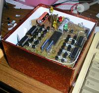
This slightly unusual design which resorts to pairing two transistors on each pin of the test IC, was the second IC tester
project that I chose to construct. The individual transistors allow the test IC to be automatically powered in any pin configuration,
as well as presenting the usual test stimulus to its inputs. While this approach does avoid any effort being required of the
user to manually configure unusual power pin configurations, it also means that an error causing an input signal to be sent to
an output of the test IC will short that output and potentially damage it. It also means that if some error or glitch makes
two of the drive transistors on a pin turn on at once, they will probably self destruct. Still, if everything works OK there
shouldn't be a problem, and mine hasn't gone into meltdown yet!
The PCB layout provided doesn't quite allow room for the common "lever operated" ZIF socket, unless a spacer of some sort is
used to raise it above the nearby 74150 demultiplexer IC. This IC may not be quite as easy to obtain as the 4/4 component
availability rating that I've given this project might imply, but it's a standard 7400 series part and I was able to buy it
for a reasonable price from RS Components.
The software allows quite a lot of flexibility for the user, as long as they don't mind the command-line interface. The
ability to manually specify individual data sequences to be written to the IC, and read them back, opens the option of using
the software in scripts to extend the existing functionality which of course includes the usual testing of known ICs using
premade test files. It doesn't currently offer automatic IC model identification, though the IC dump functionality which creates
"dump files" of ICs may have been a part of an unfinished system for doing this without a complete library of ICs truth tables.
Look at my notes for some more specific comments.
John Bibin, Java+ATmega32 IC Tester |
|
| Published | Author | Component Availability | PCB Layout? | ICs Used | ICs in Test Library | Max. Test Pins | Type |
| 2006 | John Bibin, P. R. Balsaraj, K. S. Athul, K. M. Anil | 4/4 | No | 1 | >20 | 24 | PC Controlled Active |
- Very simple (perhaps a little too simple) design connecting a test socket to an ATmega32 microcontroller
- Connects to PC parallel port and is controlled by Java software (no longer downloadable)
|
- Test IC power, as well as test IC input signals supplied automatically by ATmega outputs connected directly to the
test IC (this could be an issue when testing TTL ICs)
- No pull-up resistors for testing Open-Collector outputs
|
|
Based on an ATmega32, this extremely simple design may seem attractive but for the broken download link for the PC Java
software (firmware code for the microcontroller, written in Assembly, is listed in the university paper on the webpage ("Report" link at the bottom)). However its approach,
of connecting the ATmega's I/O ports directly to the test IC to supply both power and test inputs to it, has some limitations
that are not stated (as far as I can work out from the badly broken English) in its co-designer's description.
Most particularly, although the ATmega32 can supply enough current to power common TTL logic ICs, a minimum High output
voltage specification of 4.2V, along with a maximum Low spec. of 0.7V means that the test IC may only receive 3.5V between
its supply voltage pins. While this is OK for testing 4000 series CMOS ICs which can operate at this low voltage, 7400 series
ICs will be well below their specified operational voltage range, and unreliable operation is extremely likely irrespective
of the test IC's actual condition. The voltages on the ATmega's outputs probably won't be as bad as these worst case ratings,
but it is very likely that the supply voltage will not be high enough to meet the 4.5V minimum of the 7400 logic series. To
ensure failed tests can be trusted, power pins should be manually wired to 5V and GND using a patch lead arrangement, or extra
circuitry added to achieve a similar effect.
Other issues include a risk of damaging the ATmega32 if an IC with shorted inputs is tested and overloads the microcontroller's
I/O port/s. If not using the ATmega to power the IC, as I suggest for use with 7400 series logic, resistors on IC test pins
in a similar arrangement to many other testers listed here could be added to the design. The constructor is still left with
the task of writing PC software to interface with the device though, as the original software seems to have fallen through one
of the gaps in the "World Wide Web".
8051projects.info, PC Based Digital IC Tester |
|
|
| Published | Author | Component Availability | PCB Layout? | ICs Used | ICs in Test Library | Max. Test Pins | Type |
| 2008 | Anonymous? | 4/4 | No | 2 | 6 | 14 | PC Controlled Active(sort of) |
- Based around an 8051 derivative microcontroller, communicates with PC via Serial Port
- Only supports a small, unexpandable, set of 7400 series ICs for testing (7400, 7402, 7404, 7408, 7432, 7486)
- Test IC power pins are hardwired in the most common power pin configuration for 14pin 7400 series ICs
|
- Pull-up resistors to suit testing Open-Collector outputs
- No resistors on microcontroller's outputs to protect them in case of shorted IC inputs or incorrect test data
- Firmware code provided in MCS-51 Assembly, and as an assembled binary for programming to the microcontroller
|
|
This simple design is limited to a specific set of ICs which can be tested, by it's available software that must be
modified to support more ICs, its hard-wired power pin configuration, and its use of just a 14 pin IC socket. The testing
is done by code in the microcontroller, the PC software just instructs it as to the model of IC to test and reads back the
results. This means that to extend the range of supported ICs, both the microcontroller firmware and the PC software must be
modified.
The I/O pull-up resistors in this design were probably included due to the limited current sourcing ability of the
microcontroller's outputs, but they also allow the testing of ICs with Open-Collector outputs that match the pinout of
ICs with totem-pole outputs. These aren't including in the list of supported ICs, but as well as the cloned IC models (where
two IC models have the same function and pinout), and some pin-compatible CMOS devices, they could likely be checked by telling
the tester to perform it's tests designed for their compatible cousins.
Registration is required to download the software, however if, like me, you don't like registering at websites, a look at
the webpage source code might lead you to determine an alternative method of downloading the ZIP archive. Note in particular
the difference between the URLs for the ZIP download that doesn't work, and the image files that do. :)
8051projects.info, Digital IC Tester for 74 Series |
|
|
| Published | Author | Component Availability | PCB Layout? | ICs Used | ICs in Test Library | Max. Test Pins | Type |
| 2009 | Binu J | 4/4 | No | 2 | 139 | 16 | Active |
- Based around an AT89C55 (8051 derivative) microcontroller
- IC model entered on keypad and results shown on LCD display
- Three relays automatically select between common power configurations
- New IC test data can only be added by modifying and reprogramming the microcontroller's firmware code
|
- Shows test results for individual gates on simple ICs
- Pull-up resistors to suit testing Open-Collector outputs, and test I/O buffer resistors to protect against
shorted ICs etc.
- Provided assembly firmware only tests 7400 series ICs, no test data for 4000 series (hardware might be capable of testing
them)
|
|
A much more complete tester from the same source as the previous entry. This design is controlled entirely by the AT89C55
microcontroller receiving the model of the test IC from a keypad and displaying results on a standard 16x2 LCD display. The comprehensive
set of test data is all programmed in the microcontroller's firmware, and strangely omits any tests for 4000 series ICs. Perhaps
this was due to an issue discovered in testing CMOS ICs, but there doesn't seem to be any obvious hardware limitation looking
at the schematic. A user could try testing 4000 series ICs that share the pin-outs of supported 7400 series ICs.
Test IC power is configured by one of three relays with their coils driven by a ULN2003 transistor array, there is no facility for
connecting power to ICs which use a different power pin arrangement than the three automatically selected. In an improvement over
the previous tester from this website, buffer resistors are provided to protect the microcontroller's outputs, as well as pull-up
resistors for ICs with Open-Collector outputs (they know how to make me happy). When ICs with multiple individual logic gates
are tested, the result for each gate is shown on the LCD display.
The firmware for the microcontroller is only supplied as the assembly source code, and must be processed by an assembler before
it can be programmed into the AT89C55's ROM. Registration is required to download this source code, however if, like me, you
don't like registering at websites, a look at the webpage source code might lead you to determine an alternative method
for downloading the ZIP archive. Note in particular the difference between the URLs for the ZIP download that doesn't work and
the image files that do. :)
Electrofriends.com, Digital IC Tester |
|
|
| Published | Author | Component Availability | PCB Layout? | ICs Used | ICs in Test Library | Max. Test Pins | Type |
| 2012? | ? | 4/4 | No | 11 | 5 | 20 | Active |
- Design based on two 8951 microcontroller ICs, derivatives of the 8051
- Test IC power pins automatically powered in any configuration directly by 8951's I/O pins (may cause incorrect
test results)
- Test IC number is entered on an integrated keypad, with IC number displayed on LED display. Test results shown
with four LEDs.
|
- Internal IC test library can store test sequences for up to 150 ICs. Can only be updated by reprogramming
microcontroller ROM
- Code in MCS-51 Assembly is provided for the 8951 microcontrollers.
- Test sequences are programmed directly as code for the "slave" 8951, the code provided only tests five ICs,
so it must be extended to test other ICs.
- No pull-up resistors for testing Open-Collector outputs
|
|
This stand-alone tester is designed around the 8951 (or 89C51) derivative of the popular Intel 8051 microcontroller. Two
8951s are used, one to interface with the actual test IC and the other to communicate with the keypad and display. The test IC
is powered by its respective 8951 as well as provided with its test signals. This does show the versatility of the 8951
microcontroller, but I'm uncertain about the wisdom of powering the test IC through the microcontroller. For 7400 series ICs in
particular, the limits on current consumption and supply voltage caused by this power arrangement will likely put them outside their specified
operating parameters. At least no damage to the 8951 is likely if an input is shorted, because the test IC's supply voltage
will likely be delivered through an internal resistor in the 8951. ICs with their positive supply voltage pin in the
section of the socket connected to the 8951's Port 0 may be unable to be tested, because positive voltage can only be
supplied from this port under specific circumstances.
Most of the ICs used in this design are in the display circuitry for the five 7-segment LED display modules. The nine ICs
used in the provided design could be significantly reduced by using a multiplexed display arrangement perhaps based around the
4500 logic series which includes a number of ICs created to simplify this task. Of course as the display does nothing more than
show what you've typed, it may be reasonable to consider not including it at all, given the extra complexity introduced.
To add test data to the test library, the test procedure must be coded in MCS-51 assembly and appended to the relevant area
of the provided code for the "slave" microcontroller which interfaces with the test IC. This microcontroller must be removed and
have its ROM reprogrammed with a suitable programmer in order to update the test library. It is therefore impractical to use this
design for regularly testing different IC models, unless significant work is put into increasing the size of the test library.
Tauntek, LogICTester |
|
| Published | Author | Component Availability | PCB Layout? | ICs Used | ICs in Test Library | Max. Test Pins | Type |
| April 2012 | Bob Grieb | 4/4 | No | 6 | 226 | 32 | PC Controlled Active(Sort of) |
- Design based around two PIC18F2420 microcontroller ICs
- Measures analogue voltage values of test IC outputs, and also inputs
- Measures current consumed by the test IC
- Test IC power pins automatically powered in Eight common configurations. Other configurations not supported
- Controlled via RS-232 Serial Port by any terminal or terminal emulation software (platform independent)
|
- IC test data stored in microcontroller ROM, no facility for adding new tests
- Pull-up and pull-down resistors for testing ICs with Open-Collector or Three-State outputs
- Schematics provided, but microcontroller firmware only available for sale pre-programmed onto the PIC18F2420s,
along with a Circuit Board
- Tests some SRAM ICs, as well as TTL and CMOS logic
|
|
This is probably the most comprehensive of the recent DIY IC tester designs, offering some of the analogue voltage sensing
features of the much earlier "Electronics Now!" T1004 tester, with only a fraction of the components (though it does use
quite a few resistors). Although it doesn't quite match the complete feature set of that earlier design (no output under load
or hysteresis checks) this tester offers the key function of displaying the exact voltage values for each pin of the test IC, and
by biasing the pins in a voltage divider arrangement, it can even detect minor shorts in IC inputs as well as outputs.
The design includes an unusually large 32 pin ZIF IC socket. Unfortunately the analogue voltage readings can only be performed
on the lower 19 pins of the socket, so ICs with over 20 pins would partially undergo only a purely digital test. This however caters
for the vast majority of common logic ICs. Another limitation is found with the power pin configuration circuitry, as although its
automatic transistor switched design allows for quick and simple operation, no manual alternative is provided for ICs with
non-standard power pin positions.
While the above limits IC compatibility to a small degree, compatibility with control computers is excelent because only common
terminal emulation software (or a terminal itself, if you still keep that sort of thing handy) is required to control the tester
and read the results, all the processing being done by the PIC microcontrollers on the board. The interface is a command-line
one, but the commands required are few and simple. Unfortunately they don't include any method for adding new test data for
ICs not in the provided library, though this library is one of the most extensive at over two hundred ICs (the author has told
me that he may be able to provide assistance to users who require additional ICs to be added to the firmware). A serial
connection is required using RS-232. For computers without a serial port, a USB-Serial FTDI adapter cable should provide a
means of interfacing with the tester.
Techno India, Digital Integrated Circuit Tester |
|
|
| Published | Author | Component Availability | PCB Layout? | ICs Used | ICs in Test Library | Max. Test Pins | Type |
| June 2013 | Anindya Bhattacharya | 4/4 | No | 1 | ? | 14 | Active |
- Based around AT8951 microcontroller
- Test IC selection limited to ICs with a two digit suffix (eg. you could have 7474, but 74174 would be too
long to enter)
- Results shown on LCD display, including the condition of individual gates in simple Logic ICs.
|
- IC test selection entered with keypad
- Fixed power pin locations
- Microcontroller firmware must be modified to add new IC tests
- Schematics provided, but no firmware.
|
|
This is yet another overly simplified design. Although it provides a somewhat promising user interface with a keypad and
LCD display, it only allows 14 pin ICs with standard power pin positions to be tested. It also connects the IC's inputs
directly to the microcontroller outputs. As a result of this, if a shorted IC is inserted, or the wrong test is selected, and
the the microcontroller tries to pull low an IC pin that is high, it could damage either the test IC or the microcontroller.
Better designs based on microcontrollers with the 8051 architecture can be found elsewhere on this page.
EngineersGarage, Digital IC Tester |
|
|
| Published | Author | Component Availability | PCB Layout? | ICs Used | ICs in Test Library | Max. Test Pins | Type |
| 2014? | Mohit Mishra | 4/4 | No | 1 | 6 | 14 | Active |
- Based around LPC2148 ARM7 microcontroller
- Tests a very small fixed set of Six 7400 series ICs programmed in the LPC2148, microcontroller's firmware (7400, 7402,
7404, 7408, 7432, 7486)
- Results shown on LCD display
|
- Individual buttons for the user to intiate the correct test for the inserted IC
- Microcontroller firmware must be modified to add new IC tests
- Schematics and firmware available, but registration at website required to access full information
|
|
A dead simple design with numerous limitations. The 14 pin test socket is connected directly to the microcontroller's outputs.
This risks damage to the microcontroller outputs if the tested IC inputs are shorted to Ground or Supply voltage, or the wrong
test is selected. The IC is powered automatically by the microcontroller's outputs, these are unlikely to supply a high enough
supply voltage level to 7400 series TTL ICs that are tested, when the microcontroller is powered from a 5V supply.
Microcontroller Based Integrated Circuit Tester |
|
|
| Published | Author | Component Availability | PCB Layout? | ICs Used | ICs in Test Library | Max. Test Pins | Type |
| Feb. 2015 | Yousif Taha Yousif Elamin, Abdelrasoul Jabar Alzubaidi | 4/4 | No | 1 | 3 | 14 | Active |
- Based around ATmega32 microcontroller
- Listing of firmware in BASCOM language is provided
- Results shown on LCD display
|
- Test selection made using a keypad
- Microcontroller firmware must be modified to add new IC tests
|
|
Another inadequate university design. The authors appear to have ripped a lot of the text in their paper from the "Techno
India, Digital Integrated Circuit Tester" above, and it's notable that they couldn't even find a better project to plagiarise.
They did at least adapt the design to the ATmega32. Although only a block diagram is provided, I've put this in as a complete
project because the full circuit shouldn't be hard to work out based on the firmware code (especially if you refer to the
Techno India circuit, as they inevitably did). I don't know why you'd want to though, this design still has all the failings
mentioned of the Techno India tester. Other designs described here are far more useful.
electronicsforu.com, Digital IC Tester with Embedded Truth Table |
|
|
| Published | Author | Component Availability | PCB Layout? | ICs Used | ICs in Test Library | Max. Test Pins | Type |
| April 2016 | Bhaskar Jyoti Borah & Rajib Biswas | 4/4 | Yes, 1xSS | 1 | 48 | 20 | Active |
- Based around Arduino Mega ADK development board (ATmega2560 microcontroller)
- Controlled using keypad
- Results shown on LCD display
- Test IC automatically powered by microcontroller's outputs (may cause false results with 5V TTL ICs)
|
- Can identify unknown IC models
- Microcontroller firmware must be modified to add new IC tests
- Schematics, PCB layout and firmware available on project's webpage
- Microcontroller has internal pull-up resistors, which can be used for testing open-collector outputs
|
|
A basic tester designed around a popular "Arduino" development board. Like many such simple microcontroller projects, the test IC is powered directly by the
microcontroller's outputs, which have no protection against shorted inputs or power pins in the test IC. This design means that a damaged IC may destroy one of
the microcontroller's outputs when it attempts to supply power to it. The limited high (min. 4.3V) and low (max. 0.9V) output voltages of the microcontroller also
mean that TTL ICs designed for operation on a 5V supply may well be supplied with less than their minimum rated (4.5V) supply voltage, and this may cause some
working ICs to fail tests.
The interface provided uses menus displayed on a small LCD screen. The precise model of IC to be tested can be specified, or automatically detected. Results are
shown indicating the condition of individual gates as well as the whole IC. Adding new tests requires reprogramming the microcontroller firmware, though this can
be done "in-circuit". A PCB layout allows the easy construction of the design as a "sheild" for the development board.
This section does not yet include designs published online.
Electronics Today International (Australia), Linear IC Tester |
|
| Published | Author | Component Availability | PCB Layout? | ICs Used | ICs in Test Library | Max. Test Pins | Type |
| Aug. 1974 | Barry Wilkinson | 4/4 | No | 1 | 8 | 8 | Active |
- Tests commonly available (in the mid '70s) 8pin Op-Amp ICs, including the 741
- Checks Op-Amp Offset Voltage, and offset current, with readings displayed on a panel meter
- Tests Op-Amps in an internal oscillator circuit
|
- IC pin-outs and test modes selected using two 2-pole, 3-position rotary switches
- Tests: 301, 307, 308, 709, 741, 748, 777, 1456
- Can not test Op-Amps with different pin-outs
|
|
Although called by the general name of "Linear Tester", this design only suits the testing of Op-Amp ICs, not other types of
Linear IC such as Monostables. More specifically, it only tests eight-pin Op-Amps with one common pin arrangement. Nevertheless
it is able to test eight Op-Amps popular at the time of publication, and likely a few later ones that shared the same common
pin-out. In a change from the "pass/fail" nature of Digital IC testers, two characteristics of the test IC are measured. The
Offset Current and Offset Voltage readings are read on a center-zero panel meter and compared to the maximum ratings
specified in the article (or in datasheets, if unlisted later models are tested). Then an oscillator mode uses the test
IC in an oscillator circuit, the output of which is displayed on the panel meter by the needle sweeping back and forth at a
rate of around 1Hz. The circuit therefore provides both evidence of the Op-Amp performing correctly in a simple circuit, and
that it still conforms to two key operating characteristics.
Along with the 3-position switch used for selecting the test mode, another is used for selecting the compensation circuit
to suit the model of Op-Amp being tested. Many early Op-Amps required external components for frequency compensation in linear
circuits, and the circuits for these varied. The compensation switch allows two common compensation circuits to be switched
in where required, while the "A" position is for Op-Amps with internal compensation (such as the still popular 741, also the
sole IC used inside the tester). Later Op-Amps may also be suitable for testing in this device if they have internal frequency
compensation (or share the same compensation circuit), and share the same pin-out. Reference should be made to the datasheet
to determine compatibility before connecting any Op-Amp that isn't officially supported.
Practical Electronics, 741 Tester |
|
| Published | Author | Component Availability | PCB Layout? | ICs Used | ICs in Test Library | Max. Test Pins | Type |
| Apr. 1978 | T. Smales | 4/4 | No | 0 | 1 | 8 | Passive |
- Tests only the 741 series Op-Amp
- Manual test operation by changing switch and potentiometer settings
|
- Gain, and optionally Offset Nulling, can be varied
- Test IC outputs displayed on two LEDs, showing either polarity
|
|
This is an extremely basic tester for the popular 741 Op-Amp. Switches and potentiometers allow a variable input voltage to
be fed to either input while Gain, and optionally Offset Nulling, are fiddled with manually. Two LEDs allow the output
voltage in either polarity to be roughly judged based on their brightness, while a multimeter can be connected for more
accurate measurement.
Although very basic, this circuit could easily be constructed if you find yourself with a bulk lot of questionable 741s.
Hopefully you end up with more than two good chips for your efforts, unlike the project's author.
Practical Electronics, 555 and 741 Tester |
|
| Published | Author | Component Availability | PCB Layout? | ICs Used | ICs in Test Library | Max. Test Pins | Type |
| Sep. 1983 | Stephen Ibbs | 4/4 | Yes 1xSS | 1 | 2 | 8 | Active |
|
|
- Simple oscillator circuit proves basic IC operation
|
- Output displayed on one of two LEDs (from 555 or 741)
|
|
There's not much to this IC tester, which is really just the standard 555 tester design found all over the web today, but
with a 741 Op-Amp connected to the output so that it can effectively buffer the 555's output. Compared to other Op-Amp testers,
there is no scope for measuring individual parameters, while for the 555 the Control and Reset pins are not tested, and the
operating frequency can only be compared visually. All the same, odds are high that most faulty chips would be picked up by
such a tester, and it would be a quick build, with the circuit board layout making construction even easier.
A working 555 is required when testing 741s in order to provide the input signal. For testing just the 555, you could
say that the number of ICs required is zero.
Electronics Now! (R-E), Analogic IC Tester |
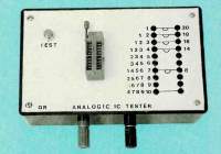
|
| Published | Author | Component Availability | PCB Layout? | ICs Used | ICs in Test Library | Max. Test Pins | Type |
| April 1996 | Rick Duker | 4/4 | Yes, 1xSS | 0 (20 transistors) | N/A | 20 | Other |
- Tests both Logic and Linear ICs.
- Does not check the IC's complete function, only the internal PN Junctions of each pin. Based on the theory
that the failure of these is the cause of most IC malfunctions.
|
- Simple operation. Insert IC, press test button, and condition of all pins is indicated at once on individual
LEDs.
- Also tests diodes, transistors, and basic tests for inductors and capacitors.
|
|
This unusual design works on the assumption that most IC failures are caused by the PN junctions at their inputs and outputs.
In testing these, it does not need any circuitry or test configurability to determine the correct operation of the IC's functions,
instead simply providing indication on LEDs of the PN junction characteristics of each pin. For digital ICs the failure of an
LED to light for a pin will usually indicate a failed PN junction there. Linear ICs may give more complex readings when in good
condition, so a known good IC of the same model and manufacturer must first be inserted, and its reading compared to the suspect
IC manually to observe any differences.
This tester does not claim 100% certainty of the condition of ICs that pass its test, however it is expected to pick up
the majority of failures.
These are projects where not enough information has been made available for the device described to be constructed by the
reader. They are included for completeness, and as a source of ideas.
University of Limerick, Software / Hardware Digital Based Functional IC Tester |
|
|
| Published | Author | Component Availability | PCB Layout? | ICs Used | ICs in Test Library | Max. Test Pins | Type |
| ? | R. Strunz, D. Toal, C. Mc Gowan | ?/4 | No | ? | ? | 24? | PC Controlled Active |
- Supports testing ICs with a supply voltage of +5V, +15V, or -15V, automatically switched to power pins using
Optoisolators
- Test signals applied to test IC inputs using AD7511 CMOS Analogue Switches, protected with foldback current
limiting
|
- Software includes a flexible test data editor which displays test signals as a timing diagram and allows copying
and pasting sections of test data
- No schematic or software. Paper contains screenshots of the software and a block diagram for the tester
|
|
There once was an IC checker,
It knew its bad chips from the better.
But to hide its design,
Was oh such a crime.
Now it's stuck in this IC test mecca.
Oh alright, you've heard better ones, I couldn't resist doing something to accompany a design from the University of
Limerick. Perhaps in preemptive retribution for the poor rhyming skills to be used against it, all that we have to describe
this tester is the paper published on the University's website (although, it would seem, minus a page or two) for long enough
to get caught by the Wayback Machine and kept in its archive for us to puzzle at today.
Indeed much like a bad limerick, it leaves the reader wondering exactly what some parts really mean. However the only
truly notable feature to distinguish it from other testers appears to be the ability to test ICs at one of three supply
voltages (+5V, +15V, -15V). Analogue switches of the type AD7511 are apparently used to interface with the test IC's inputs
and outputs, but the exact arrangement is unknown. Like some of the other tester designs, this interfaces with the PC using an
8255 Parallel Interface IC, though the type of port used to connect it to the PC isn't known.
Electronics Club IIT Kanpur, Digital IC Tester |
|
|
| Published | Author | Component Availability | PCB Layout? | ICs Used | ICs in Test Library | Max. Test Pins | Type |
| ? | Abhishek Jain, Anshul Goyal, Siddharth Garg | 4/4 | No | 2 | 15 | 16 | Active |
- Based around two ATmega16 microcontrollers
- No firmware or schematics provided
- Results shown on LCD display
|
- Test selection made using a keypad
- Microcontroller firmware must be modified to add new IC tests
|
|
A project by an "electronics club" at the Indian Institute of Technology Kanpur. It uses two ATmega16 microcontrollers, one
for the keypad and display, the other for performing the tests. The circuit isn't provided, but I suspect that I'd pick faults
with it. They have at least bothered to program tests for fifteen ICs, and include support for sixteen pin chips, but really
there isn't anything innovative about this design as far as it is described. Using "www.google.com" as a reference is a good
laugh!
Margoo's Universe, PC Based Tester For TTL & CMOS Logic Devices |
|
|
| Published | Author | Component Availability | PCB Layout? | ICs Used | ICs in Test Library | Max. Test Pins | Type |
| 1996 | D. M. Brewer | ?/4 | Yes, 2xDS - not available | 10 | ? | 24? | PC Controlled Active |
- Connects to PC via Parallel Port
|
- Tests TTL and CMOS logic, identifies TTL but not CMOS ICs
|
|
Another university project captured by the Wayback Machine, but this one is written up by the author on their old Geocities
website. Two pictures show the device which is split between two double sided PCBs. The IC count I put in the table is based on
these images, but there are two empty sockets on the test board which might suggest an additional pair. There were a couple of
block diagrams on the web page, but the Wayback Machine let them escape its archival net. It doesn't appear that any design
information was published such as schematics or software.
The functions appear to be fairly standard for a PC controlled tester, nothing particularly unusual.
John Bibin, C+Parallel Port IC Tester |
|
|
| Published | Author | Component Availability | PCB Layout? | ICs Used | ICs in Test Library | Max. Test Pins | Type |
| ? | John Bibin | ?/4 | No | 9 | ? | 16 | PC Controlled Active |
- Connects to a PC Parallel Port using discrete ICs, some of which are not specified.
|
- Software written in C for MS Windows
|
|
This design pops up frequently in web searches, but like the previously mentioned ATmega32 based tester from the same author,
the important download links appear not to have been saved anywhere when geocities was closed down. They may have contained
better descriptions of the tester's design, but equally may have just contained the software to run it.
The PC controlled design is represented by one vague diagram showing model numbers for some ICs but not others. The exact
capabilities are unclear.
Bharati Vidyapeeth Deemed University, IC Tester Using 89S52 Microcontroller |
|
|
| Published | Author | Component Availability | PCB Layout? | ICs Used | ICs in Test Library | Max. Test Pins | Type |
| Nov. 2012 | M. A. Tarkunde | ?/4 | No | ? | ? | 20? | Active |
- Tests a set of 7400 series ICs programmed in the 8051 derivative microcontroller.
- Microcontroller firmware must be modified and reprogrammed to add tests for more ICs
|
- Test IC selection made with four-key keypad, and results shown on 16x2 LCD display
- No schematics for microcontroller firmware available
|
|
Another vague description in broken English without any detail to allow replication of the device. In any case there seems
to have been nothing particularly notable in the features of this basic active tester design. Interested 8051 fans are referred
to the 8051projects.info tester from 2009, which shares similar design features.
Vaughn Aubuchon, Hollywood All-Jumps Tester |
|
|
| Published | Author | Component Availability | PCB Layout? | ICs Used | ICs in Test Library | Max. Test Pins | Type |
| 2013 (designed in 1977) | Vaughn Aubuchon | 2/4 | No | 38 | 31 | ? | Comparison |
- Designed to test programmable ICs, not standard Logic ICs. Tests ROMs, PROMs, PALs, and PLAs.
- Variable supply voltage to the test IC.
- Originally designed for internal use by IC manufacturer "Monolithic Memories".
|
- Tests the timing characteristics (AC characteristics) of the IC, as well as whether the data programmed onto
it matches the "reference" IC which it is compared against.
- Adapters used to accomodate different pinouts.
|
|
This design is unusual in a number of ways. Firstly, although it was published only recently on the author's website,
it was in fact designed and built at the facility of his then employer "Monolithic Memories" in 1977. This unusual origin
for a (semi)published design explains its much more specific role than that of most other complex testers on this page.
As a device for testing programmable ICs, it requires a "known good" device to compare with as it reads off the data. The
address range (or logic inputs, for programmable logic ICs) is advanced during this process by the automatic clocking of DM8556
counter ICs. In addition to this basic check of the programming, the tester also determines the AC Characteristics of the test
IC at various supply voltages. A precision one-shot timer is configured to sample the IC's outputs a specified number of
nanoseconds after the address inputs are applied, allowing the minimum time required for accurate output data to be determined.
The test sequence is controlled by a network of one-shot timers, and in the event of a miss-match between the outputs of
the reference IC and the test IC when sampled after the specified delay, the address counter stops at the location of the
error. The operation that caused the error can then be repeated continuously while the signals are viewed on an oscilloscope.
The webpage includes a lot of information, including a block diagram, component list, and usage instructions, but there is
no schematic available.
Arduino TTL IC Tester |
|
|
| Published | Author | Component Availability | PCB Layout? | ICs Used | ICs in Test Library | Max. Test Pins | Type |
| Oct. 2013 | Dan Nelson | ?/4 | No | ? (probably 1) | 9 | 14 | Active |
- Based around Arduino Uno development board
- Only has tests for nine 7400 series ICs in the provided firmware (7400, 7402, 7404, 7408, 7410, 7420, 7427,
7432, 7486)
- Firmware must be modified and reprogrammed into microcontroller to add tests for more ICs
|
- Test two keys controlling menu on, LCD display, which also shows test results
- No schematics, just uncompiled microcontroller firmware code written in C
|
|
A simple program for one of the Arduino development boards which tests a small set of simple logic gate ICs from the 7400
series. No schematics are provided, though one can assume that direct connection of the Arduino I/O pins to the test socket
was the method most probably used by the author. A better advised design would be to include patch wires or automatic
switches for power pin configuration, and resistors on all I/O connections to the test socket, to protect the Arduino from
shorted test ICs. Pull-up resistors could be included for testing ICs with open collector outputs. Of course other designs
listed here can be referred to for more advanced hardware design ideas.
Instructables, Digital IC Tester Using PIC Microcontroller |
|
|
| Published | Author | Component Availability | PCB Layout? | ICs Used | ICs in Test Library | Max. Test Pins | Type |
| 2014 | Jestin Cubetech | ?/4 | No | ? | 8 | 14 | Active |
- Tests a very small fixed set of eight 7400 series ICs programmed in the PIC16f877a microcontroller's firmware (7400, 7402,
7404, 7407, 7408, 7432, 7486, 74266)
|
- Video and picture, but no schematics or firmware downloads available
|
|
This is a basic design for which little information has been provided. There's a video, and I must admit that I haven't
watched it. Whatever it says, I would strongly recommend that any PIC enthusiasts direct their attention to the Everyday Practical
Electronics Digital IC Tester above, while also uses the PIC16F877, but does so to much greater effect.
RAM Tester |
|
|
| Published | Author | Component Availability | PCB Layout? | ICs Used | ICs in Test Library | Max. Test Pins | Type |
| August 2015 | Dan Roganti | ?/4 | No | ? | ? | ? | PC Controlled Active |
- Designed for testing RAM and other ICs used in vintage computer systems
- Controlled by some sort of keyboard driven PC software
|
- Software unfinished at the time of the video
- No information besides the two YouTube videos (checked author's website, nothing there)
|
|
This IC tester has been designed mainly to test RAM ICs used in vintage computers. In the second video, the author says
that it can also test some peripheral interface ICs commonly used in those computers, but it's not clear if it would be
suitable for testing ICs such as discrete logic chips. There is a bank of DIP switches on the front, which may be for power
pin configuration.
It appears that no construction information was published, and
the author has since died, in September 2018.
Hackaday.io, Old School IC Tester |
|
|
| Published | Author | Component Availability | PCB Layout? | ICs Used | ICs in Test Library | Max. Test Pins | Type |
| May 2016 | Alexander Shabarshin | 4/4 | No | 6+? | ? | 32 | PC Controlled Active |
- Designed to connect to parallel I/O ports on old home computers
- Manually configured power pin connections
|
- Project appears unfinished at the time of writing
- Seems to aspire to be an EPROM programmer as well
|
|
This unusual design aims to be usable with the author's 1990s Russian clone of the ZX Spectrum home computer. So far the only schematic is a sketch
of the circuit connected to each pin of the test IC, although at least this looks fairly sensible. Manual connection of the positive power supply to the test ICs
supply pin appears to be required.
A picture is shown of a completed board, but it appears that software has not yet been developed. A decision on the bus arrangement for connecting the IC tester
board with the computer's parrallel interface appears also to be pending.
IC Test Fixture |
|
|
| Published | Author | Component Availability | PCB Layout? | ICs Used | ICs in Test Library | Max. Test Pins | Type |
| 26th Dec. 2016 | PA4TIM | 4/4 | No | 0 | N/A | 16 | Passive |
- Tests are configured by inserting "jumpers" with components soldered onto them into IC sockets
- Second version makes use of rotary switches to replace many of the IC sockets for test configuration
|
- Tests analogue and digital ICs
- Includes potentiometers for setting values on analogue inputs
- No schematic. Built on prototyping board.
|
|
This tester is designed mainly for testing unusual ICs for which other IC testers are not suitable. It simplifies manual
testing of analogue ICs, and displays the output states of digital ICs on LEDs.
There's no construction information besides pictures of version one and version two of the tester, the latter built into
a case and using rotary switches in place of IC sockets for test configuration. A very great quantity of discrete wiring
is shown in the picture inside the second version.
- Component Availability
- The rating from four is to give some rough indication of the difficulty which might be encountered by a potential constructor
of these sometimes quite outdated projects in the modern electronic marketplace. A rating of four indicates that little
trouble should be had, and an owner of a well stocked parts box may indeed find themselves with need to purchase little
or nothing at all. Three, shows that some parts would require more searching to obtain and may likely have to be ordered from
online suppliers, two indicates that the parts may have gone out of production and must be purchased as new old stock.
Finally a rating of one is reserved for designs such as the two Radio-Electronics tester designs by Bill Green, which
surprisingly relied upon custom manufactured ICs sold only for the particular projects at the time of their publication.
- ICs Used
- This does not include Voltage Regulator ICs that power the internal circuitry of the tester. These are sometimes not
included in schematics, and some designs are intended to be powered by battery or from a bench power supply. As the
exact power source can often be determined by the constructor, and today's switch-mode power supplies introduce the
possibility of the power supply already being regulated by the time it gets to the tester, it was decided that internal
voltage regulators be quietly ignored by the "ICs Used" count. Constructors of IC tester projects should consider which
power source suits them before deciding whether to follow the guidance of their project's author.
- Features
-
As much as I've tried to be consistent, don't take my failure to mention a feature that
is mentioned in other designs as conclusive evidence that the that particular feature is
not present. As might be evidenced by the varying tone of my descriptions, the entries
on this page were done over some period of time, and it's likely that some features will
have occoured to me worthy of mention while on other days the same features might not
have.
- Test Libraries
-
I find a good set of existing test library files vitally important to the selection of an
"active" type tester project. This is simply due to the unpleasentness I associate with
entering and debugging test data manually, even with the aid of the graphical test
data editors which only some designs are accompanied with.
Often, simpler logic ICs share the functions and pinouts of other models. Particularly
when one model has Open-Collector or Three-State outputs, and also between the 7400
and 4000 logic families. This should be considered when contemplating programming a
new test for an IC from scratch, because the file for another model might be trivially
adapted.
The far outstanding winner in terms of existing IC test data, is the Circuit Cellar IC
tester with a claimed 600+ ICs in the provided library files. Unfortunately, like almost
all the active tester designs shown here, the test data format used by the Circuit Cellar tester
is incompatible with every other IC tester design. There is no fundamental restriction
preventing the conversion of IC test data between the formats used by the various tester
softwares, and I hope myself to one day write a universal converter program to allow test
data in any format to be converted for use on any tester design where the data format is
known. Ideally, a test data editor would also be included, especially useful for designs
that don't come provided with one in their own software.
- IC Position/Orientation
- As is the inevitability of human design, designs make varying assumptions about how their users will insert the ICs they
want to test into their IC tester. Bottom justified, center justified, top justified, forwards, backwards, generally
enough options to drive any user nuts. Some articles make a good point of showing how ICs should be inserted, with diagrams
showing how to go about the seemingly simple task. Others, however, blindly persist in the illusion that their method
is simply obvious, an attitude which could cause the rapid death of a chip subjected to reversed power connections due
to being put in the wrong way around. If not specified in the documentation for their selected design, constructors
should look at the circuit itself to determine the arrangement that it's designer has deemed appropriate for test ICs
to be inserted in.
- Test IC Sockets
- While used with the best of intentions, the fumbling fingers of an IC tester's user may cause harm to the fragile legs
of an unfortunate chip, simply by attempting to insert or remove it from an uncooperative IC socket. As many above
designs will attest, a "Zero Insertion Force" (ZIF) socket finds a most worthy place upon the PCB of a good IC tester
build, as it is designed specifically for the purpose of temporarily connecting with an IC and allowing its easy removal
thereafter. Most common are the lever actuated type, which can command a steep price from electronic component suppliers,
enticing the more financially driven constructor to look towards standard ICs sockets intended for semi-permanent mounting
of ICs. While a perfectly valid option, these much cheaper sockets come with disadvantages including the force required
for IC insertion and removal, and the need for IC legs to be bent to the specific width required for insertion in the
socket. Further disincentive towards this compromised approach is to be found at online retailers such as Ebay, where
good ZIF sockets can be purchased directly from china for perhaps a tenth of the cost that they command on the shelves
of more mainstream suppliers. Having purchased two such sockets so far, I can confirm that they are quite satisfactory,
though constructors should note that the PCBs for some tester designs do not allow for the space taken up by a ZIF
socket.
Standard DIP ICs with tarnished legs can often be tested after moving them side to side in a "universal" ZIF socket with
slight pressure on the clamping lever, this wears away the corroded outer surface of the pins, but no doubt isn't
ideal for the socket.
Sockets for surface-mount SOIC Chips are also available, though they can command a high cost. Again, Ebay can be a
source of cheaper options and premade adapters can also be purchased, able to be inserted in a standard DIP socket.
This is a very useful approach as it not only allows both IC packages to be tested, but avoids issues with circuit
board designs not allowing for the dimentions and pin configurations of SOIC sockets. A flat IDC cable could be
soldered to the pin connections of the circuit board and connected to the adapter, avoiding the trouble that can
sometimes be experienced when using the thick pins of IC package adapters in ZIF sockets. An old IDE cable can be
sacrificed for this role, with the two IDC sockets on the end used to connect with the pin headers of the DIP adapter.
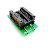
SOIC to DIP Adapter
- IC Test Clips
- Designs offering In-Circuit testing capability may often be complimented by a special clip designed to fit around the
perimeter of a suspect IC and connect with all its pins in one action. While an enticing design, these clips are difficult
to obtain. Some clips are available on Ebay, Aliexpress, etc. (search "IC Pin Clip"), however at the time of writing, only
8-pin DIP and 16-Pin SOIC clips were available particularly cheaply. The only modern manufacturers I have found making
clips for a full range of IC types are 3M, and a company called Pomona, who have test clips for
DIP,
SOIC, and PLCC
ICs.
In case you, or someone you can persuade, has a 3D printer, there are a few models available to allow you to print your own. Designs
by "Selmo", or by "Enif", can be downloaded
from the "Thingiverse" website.
- Microcontrollers/Microprocessor ROM
- When looking at microcontroller and microprocessor based projects, note that most such designs that I have found do not
include a simple In-Circuit programming method. It is therefore important that the potential constructor considers
the availability of a compatible programmer device to be used during construction (and for later test library updates
with some designs).
- Projects Missing in Action
- These are projects that I know of from article lists for magazines, but have not been able to obtain copies of. Scans
are welcome!
- Electronics Today International (Australia), Dec. 1975 - TTL Tester (compliment to CMOS Tester, which is covered
above)
- Commercial Testers
- There are of course a wide range of commercial testers available. In most cases these are targeted at industrial use,
and are priced accordingly. While some may have enough luck to find a cheap deal on a second-hand model, generally
the best options for low cost pre-built IC Testers can be found from the Chinese sellers on Ebay, Aliexpress, and other
such online retail websites. The particular model shown in the image below (known sometimes by the model number "LM399",
not to be confused with the IC manufactured by Texas Intruments) was once available for under $10 including
postage, however it has presumably gone out of production as the number of sellers has reduced, and the prices have
gone up. Other models have LCD displays which may show some extra information, but many will not describe the
exact tests performed. I believe that none of these Chinese testers allows new tests to be programmed in, though they
do seem to do automatic IC identification. Lists of supported ICs can vary, and perhaps increase over time as firmwares
are revised, this list from one Ebay item page for an LM399 type tester shows 234
supported ICs. It's unknown how comprehensive the tests performed are, they may be the minimum required for IC
identification, which would allow some partially faulty ICs to be incorrectly reported as working.
This YouTube video, which shows one LM399 type tester incorrectly
identifying an LED 7-segment display as a logic IC, indicates that the tests performed are indeed not very thorough.
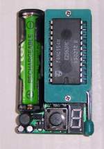
Common IC tester device (model "LM399") sold cheaply online from China a few years ago. Click for a bigger image.
While it is outside the scope of this page to provide a comprehensive reference to commercial IC tester designs, here
are a few links relating to some of them:
- The cheap Chinese testers mentioned above can be found by searching "IC Tester" at Ebay, Aliexpress, or similar
websites
- A breif video of one of the cheap Chinese LM399 testers mentioned
above, in normal use, on YouTube
- Hacking
a Chinese EPROM programmer to work as an IC tester
- Internal pictures and basic information on ABI "Digital In-Circuit IC-Tester" Commercial IC tester from the 80s - Andy's Arcade
- Pictures and basic information on later ABI "Boardmaster 4000" Commercial IC tester - Andy's Arcade
- A quick look and a very sad plea for help by someone with a broken ABI DDS-40XP commercial IC tester, on YouTube
- Forum thread relating to the above YouTube video, includes a few pictures - UK-VAC Forums
- Good internal pictures and description of the repair of an ABI IC tester from 1986 - UK-VAC Forums
- Promotional video for modern models of IC tester from ABI, on YouTube
- A review of a 1970s Heathkit IT-7400 passive IC tester kit, on YouTube
- Details on many commercial IC testers along with other test equipment
- HP10529A comparison-type in-circuit IC tester Radio Museum page, manufacturer's page, with manuals
- Details and internal pictures of a BK Precision model 560 IC tester. I also have a scan of the manual, which I picked up somewhere on the internet
- Manual for ESI Model 1248 IC Tester
- Manual for Fairy IC Tester Card for Apple II. Also here and here
- Website of ABI Electronics, main manufacturers of new commercial IC testers today
Text Content Copyright Kevin Koster 2019
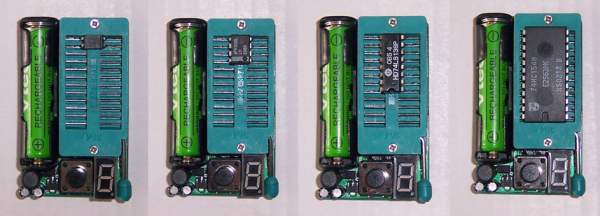
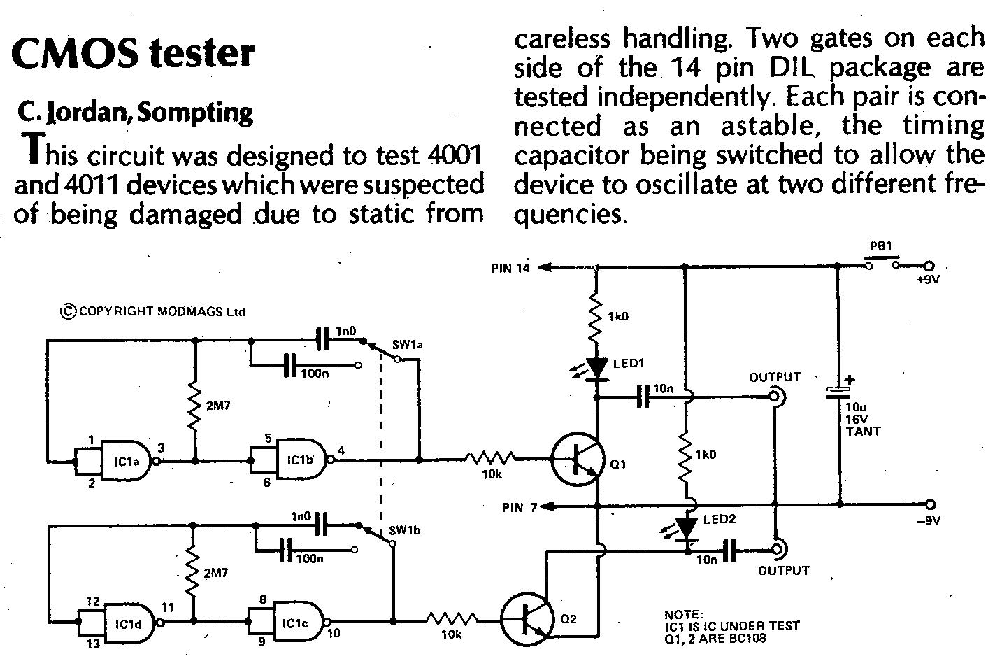
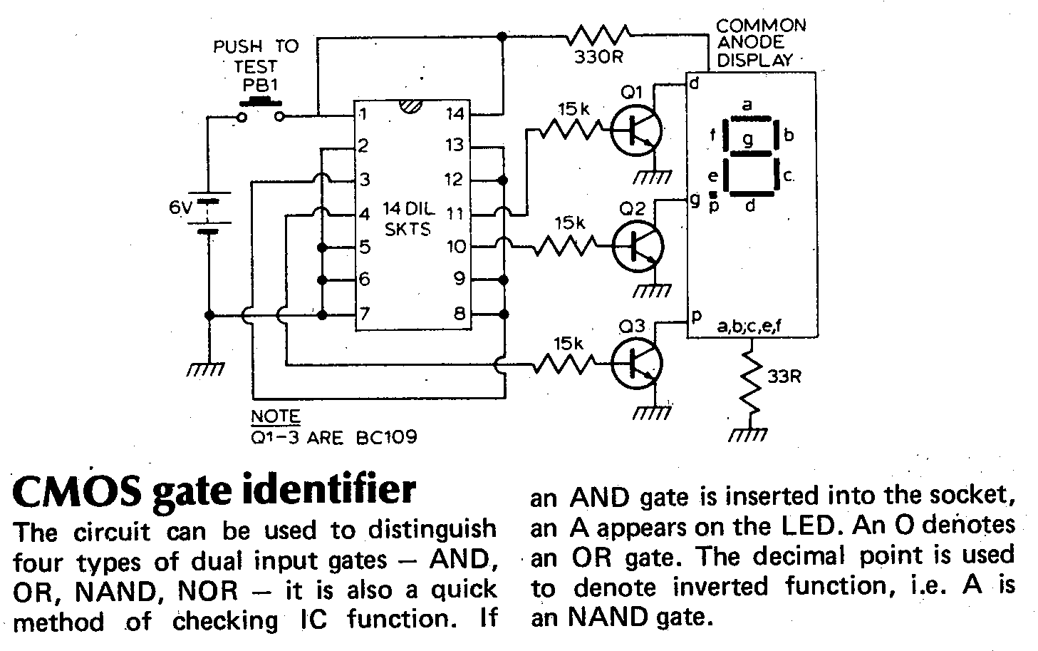