Computer Nerd Kev |
Home|About|Projects|Links |
Projects > IC Testers > SK |
Silvio Klaic's IC Tester Build Notes |
After finishing my DSA IC tester build, and debugging its faulty 8255 Parallel Interface IC, I felt compelled to build another tester which would hopefully come together without such difficulties. Although more limited in general terms, the IC tester design by Silvio Klaic offers some unusual features and room for adaptability to automated testing and other applications. Specifically, the capacity for automatic connection to IC power pins in any configuration, as well as Linux and DOS software that allows for reads and writes to be sent specifically from the command line, and potentially integrated into scripts.
To be truthful, I haven't yet had cause to capitalise on those special characteristics. In fact because of its more limited IC test library (and lack of a test editor to allow easily adding tests for additional ICs), I use it far less often than the DSA tester. However a key attraction is the Linux software, which saves me rebooting into DOS.
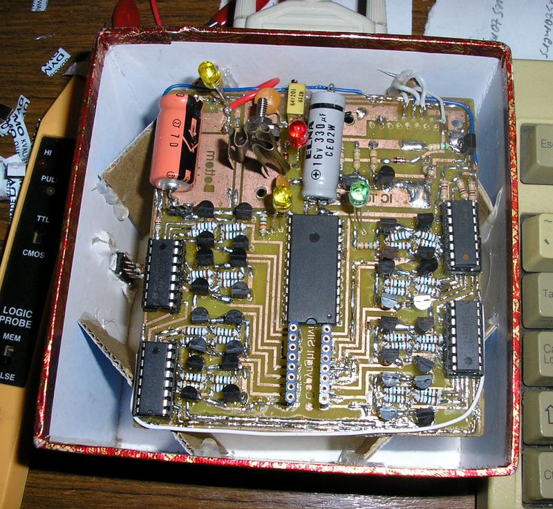
First off, if something's confusing you about the circuit board in my build, it's because I managed to etch it without noticing that I'd accidentally got it in mirror image (I always get confused by which way to flip things so that they will come out right using the toner transfer PCB making method). Luckily I figured out that if I put all the components on the bottom side of the board instead of the top, it would work, and it actually didn't make the soldering much harder than it already was because there are plenty of under-IC connections on both sides of the board. Unfortunately, this wasn't the last time that I've had to use this trick...
Like the DSA IC tester, which is more complex, this design uses separate sections of the circuit for writing and reading test data to/from the test IC. However whereas the DSA tester uses a parallel data bus to read/write eight bits of data at once using the parallel port, this design uses serial communication. The circuits for test outputs and test inputs operate quite differently, again in contrast to the DSA tester. While data is written to the test outputs by shifting into a series of four shift registers, from which two outputs are required per test pin, it is read from the test pins by a single 16:1 multiplexer IC that selects each pin to be read sequentially.
The outputs to the test IC are set by discrete BC547 NPN transistors, one pulling each pin to Vcc and the other pulling it to Ground, each connected to its own shift register output so that they can both be disabled when connected to an output from the test IC. Any transistors of type BC546, BC547, BC548, or BC549 would be equivalent in this circuit (along with many other types).
I consider the value of resistor used between the 4094 shift registers and transistor bases to be a design mistake. It is specified in the schematic as 100 ohms, which permits more current to flow from the shift register ICs than they are designed to handle, and is far more than should be required in order for the transistors to switch fully on and supply enough current to the test IC. I instead used 1.8Kohm resistors for R10-R41.
The value of these resistors was likely chosen to overcome another problem in the design, which is that in order for the test IC to be powered by a sufficient voltage at its power pins, the voltage drop over the two transistors connecting its power pins to Vcc and Ground must not subtract enough from the voltage regulator's output that the power supplied to the test IC is less than its rated minimum (4.5V for TTL ICs). The 7805 voltage regulator is specified to supply somewhere between 4.75V and 5.25V, so at its minimum output the transistors can drop no more than 0.25V before good ICs may stop working and test as damaged. Pushing as much base current as possible through the transistors is one way to combat this, but it is likely to be unreliable and variable between makes/batches of the components used to build the tester. My alternative is to modify the voltage regulator's Ground connection to insert a trimpot (preferably a precision multi-turn type) that allows the output voltage to be manually raised so that it is above 4.5V even after subtracting the voltage drop over the two transistors powering the test IC. The exact arrangement is shown in my modified version of the schematic, below.
Because the TTL 74150 IC is also powered by the 5V supply, and the outputs to the PC Parallel Port should not be excessively higher than 5V, the regulator should not be adjusted to over 5.5V in order to prevent damage. Testing the voltage over a TTL 7413 IC in the test socket while the tester outputs were set manually using the "-w" option in the PC software, I found that the voltage had to be adjusted as high as 5.46V in order to ensure more than 4.5V measured over the IC's power pins using a multimeter. This is right on the threshold of what is acceptable, and there is a risk that drift in the voltage regulator or the trimpot may cause the voltage to creep above the 5.5V maximum over time. However with occasional checking and readjustment it shouldn't rise high enough to cause any real trouble.
| No IC | 4.96V |
| 1K Resistor | 4.71V |
| 7413 IC | 4.53V |
| 7442 IC | 4.53V |
| 4094 IC | 4.92V |
These are some actual voltage measurements over test IC power pins with the voltage regulator adjusted to 5.46V output
The power supply circuit is designed to accept input from an AC plugpack. I chose to use a 9VDC plugpack rated for 300mA, which allowed me to skip D2, D3 and LED5 (the usefullness of that last LED is questionable in any case), as well as replace C4 and C3 with a single 220uF filter capacitor. C1 could probably be a much lower value in any case, eg. 22uF, though I went ahead and put in a (rather ancient) 330uF cap anyway.
I suspected that the voltage regulator might get a bit hot simply using the large copper area under C2 and C3 as the only heatsink, so I instead folded a strip of brass into something vaguely heatsink-ish and bolted that on. It worked OK, but I did have to let it stick itself rather inelegantly out the top of the case.
Perhaps because I was building the board back to front and upside down, I found it impossible to solder the under-IC connections to the 74150 IC using a socket, so it got soldered on directly. There's also no room for a fancy ZIF socket for the test IC, as the 74150 is positioned too close. I used two strips of machined pin sockets with long leads for wire wrapping, which allowed the socket to stick up high above the other components for easy access through the lid of the case. Put a chip in the socket strips while you solder them in place to make sure that the angle is correct to give the right spacing (a little adjustment to chip pins is often required to get them to go in anyway). Note that I have to watch that I don't push the test IC too far in or it becomes difficult to get it out of the grip of the machined pin sockets, but not in enough of course causes it to fail a test. It's not perfect. Another option would be to solder longer legs on a ZIF socket so that it can sit above the 74150, or use a ribbon cable and glue the socket on the tester's case.
One big advantage with contructing this board over the DSA one is that, although this is still a complex double sided PCB with a number of under-IC connections, the number of these, and espcially the number of vias, is much smaller. This makes construction easier and avoids problems with dodgy joints, which still cause trouble with my DSA tester. On the other hand, the DSA tester has the PCB layouts available in a format that could be accepted by some professional PCB manufacturers, so that's an easier route if you're not into making circuit boards yourself.
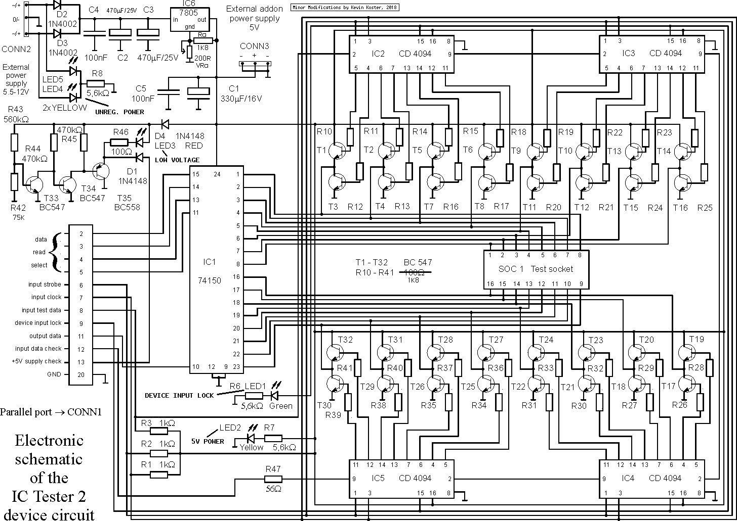
Schematic of the IC Tester with my modifications included.
Like the DSA tester, there is a test routine run with the command "ictester -t", and in combination with the documentation this allows faults to be found and diagnosed easily. For my build, an initial failure was soon fixed after I found a sneeky transistor which must have hidden one of its leads from my soldering iron during construction. After that it was all systems go!
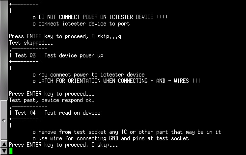
Testing the IC tester hardware
Finally, note that I believe the bottom set of transistor IDs are transposed vertically on the PCB diagram. The transistor shown as T31 is actually T29, T29 is actually T31, and so on for each pair along the lower set of transistors. This wouldn't affect construction of the board, but it might cause confusion while debugging the circuit.
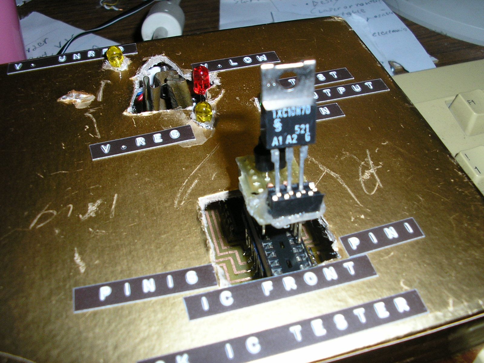
Another unique feature of this tester is being able to test diodes, LEDs, thyristors and triacs using a simple board that plugs into the IC test socket. I built this and it works well. However diodes are more easily tested by most multimeters, and I don't use many thyristors or triacs, so it hasn't got much use. Note that if you use a machined-pin IC socket for the test socket, like I did, the pin headers on this test adapter won't fit in. I have to fit a standard dual-wipe socket into the test socket, then inset the board into that, which isn't ideal. I had some test clips for a multimeter which work well for use with components that don't fit in the socket.
There's also a test sequence and instructions for this, just like there is for the main tester.
Compared to the DSA IC tester, the software for this is more basic and only offers a command line interface. On the other hand there's a version for Linux as well as DOS, which makes me happy, and it offers commands to read and write the test outputs directly from the command line, as well and executing normal tests.
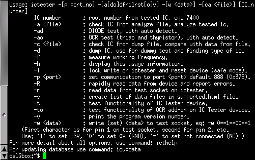
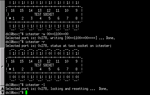
Before connecting/turning-on the IC tester, I suggest running the "ictester -l" option which ensures that the Parallel Port outputs from the PC are at a known state, otherwise they could tell the tester to turn on its outputs while invalid data is in the shift register, and if you're unlucky this could mean that two transistors on the same pin get turned on at once, causing a short and likely burning one or both of them out.
For this, and all following commands to the tester, the Parallel port is assumed to be at address "0x378", or 888 in decimal.
If, like on my PC, the parallel port you want to use is at a different address (mine's at "0x278" (632 dec.)), you need to use
the "-p [PORT]" parameter with every command. This is a bit tiring, so on Linux I set up an alias for "ictester" using this
command in .bashrc (the best way/place to set this may vary between Linux distros):
alias ictester='ictester -p 632'
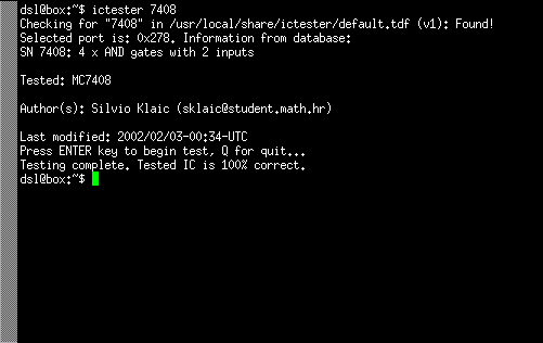
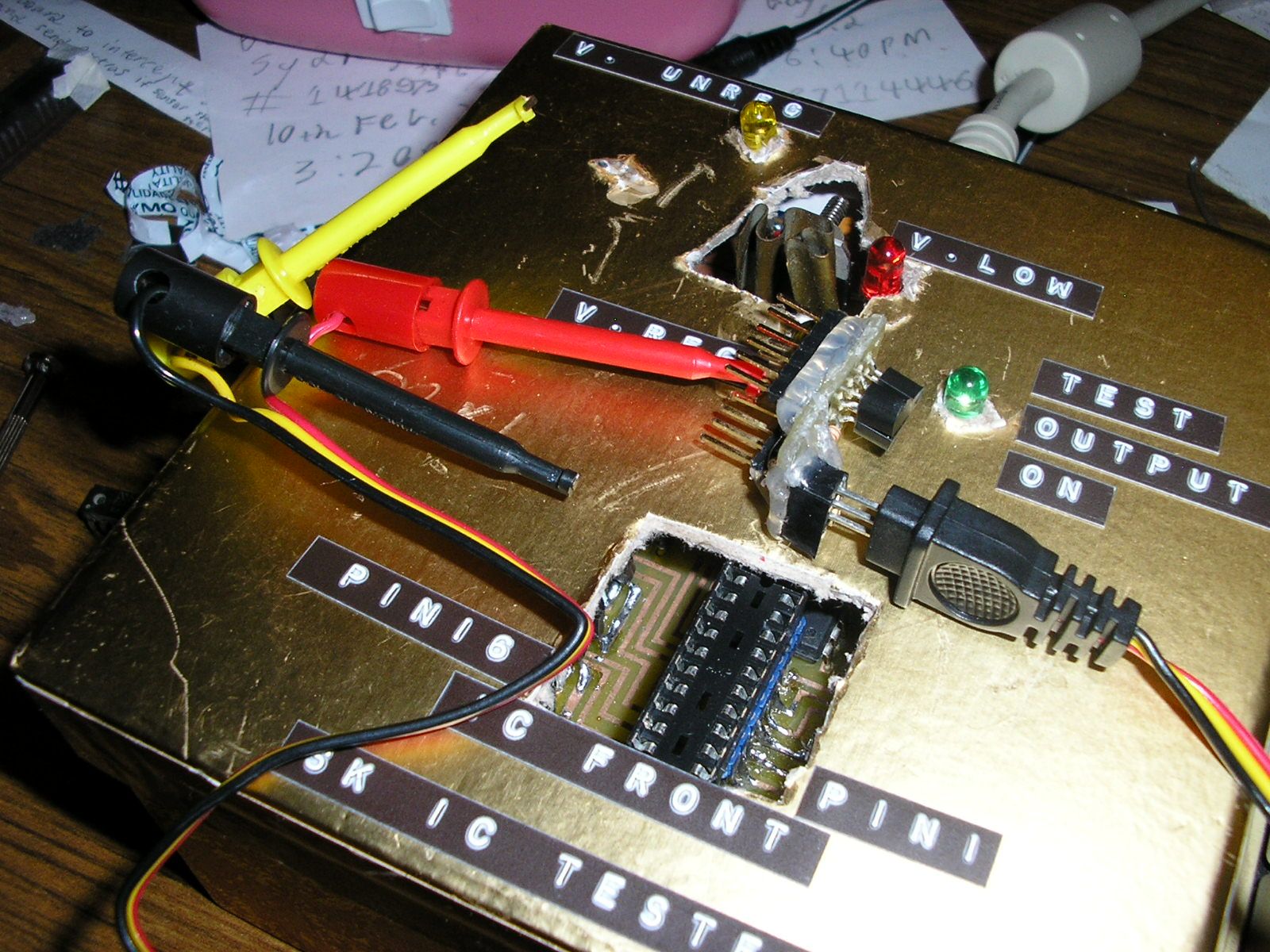
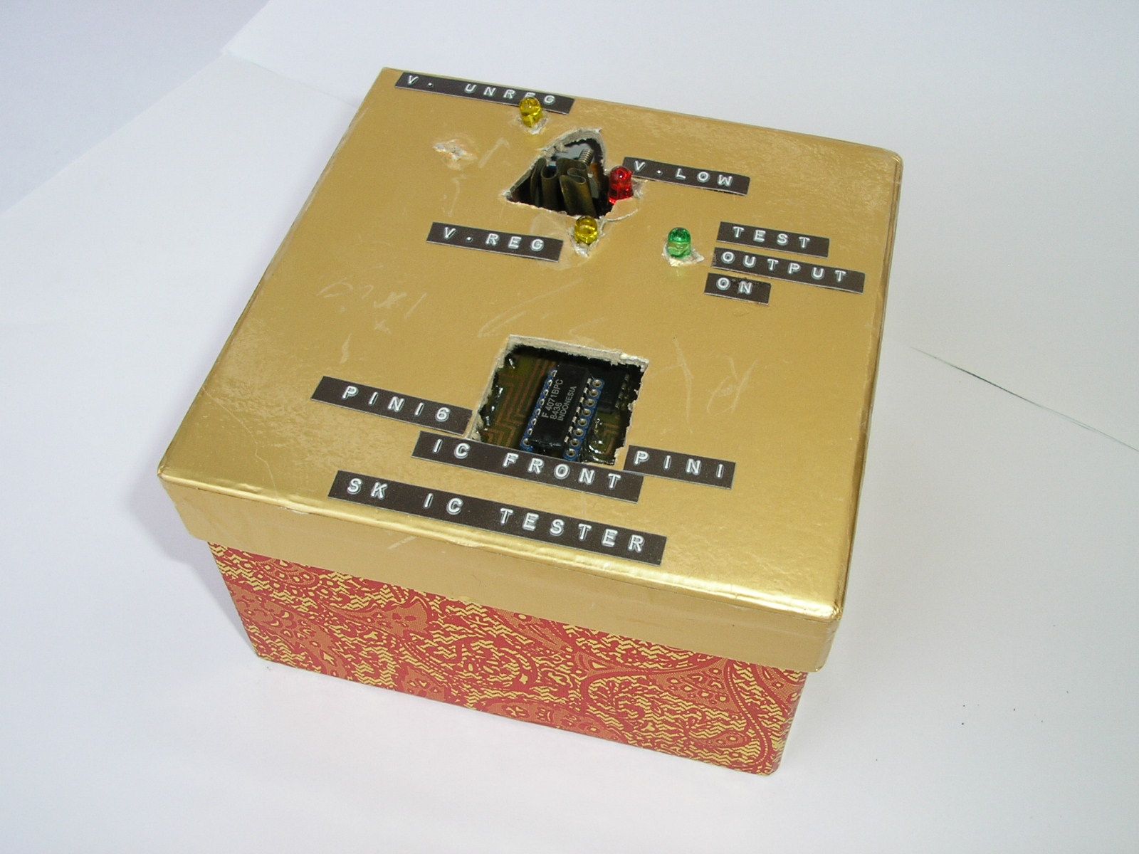
Port settings aside, testing ICs is very simply accomplished with the command "ictester [IC_NUMBER]". Eg. "ictester 7408" to test a 7408, 74LS08, 74HC08 etc. IC. One thing to be very careful of is that the IC is positioned with pin 1 towards the closest side of the circuit board, which is likely to mean facing towards the operator, and is the opposite of the DSA IC tester as well as many other designs (though there is a lot of variation with this). A wrongly orientated IC will be in grave peril as soon as the test begins, so I made sure to put labels on my tester to remind me.
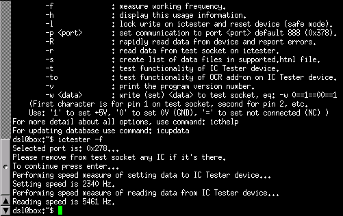
The software first checks that it has a test to match the one specified, then offers to begin by pressing enter. Testing takes significantly longer than the DSA IC tester which, running on my Pentium 1, has most ICs tested pretty much instantly. Here it takes a few seconds, the exact time depending of the complexity of the chip and the speed of your computer, but this is still quite tollerable (and you get a nice little progress indicator to watch). There's also a function to test the speed of reading and writing to the tester for comparison between computers.
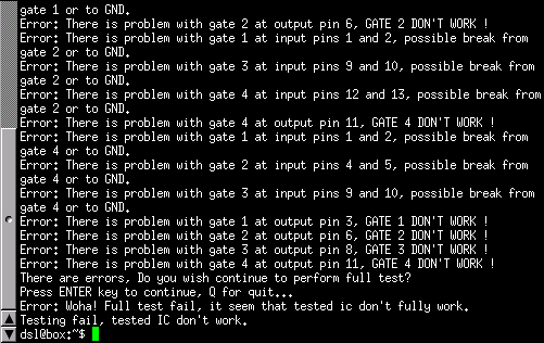
A list of failed tests is presented if a damaged IC is tested, with the option of still completing the full set of tests to determine if certain elements of the chip are still functioning. This is certainly easier than trying to catch the display of the DSA IC tester software in "debugging" mode, albeit less pretty.
The circuit board doesn't seem to have been designed with mounting really in mind. There aren't any mounting holes except those for the voltage regulator and the D-type connector. In this regard it's quite like the DSA tester's PCB, but this one isn't conveniently shaped to sit on the rim of an available ice cream tub.
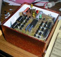
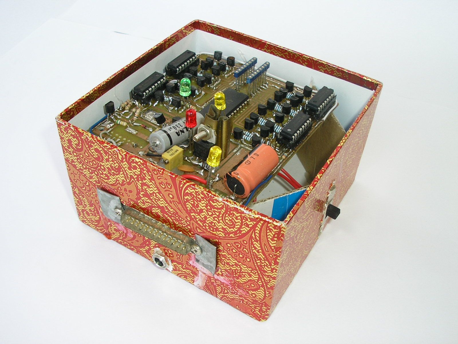
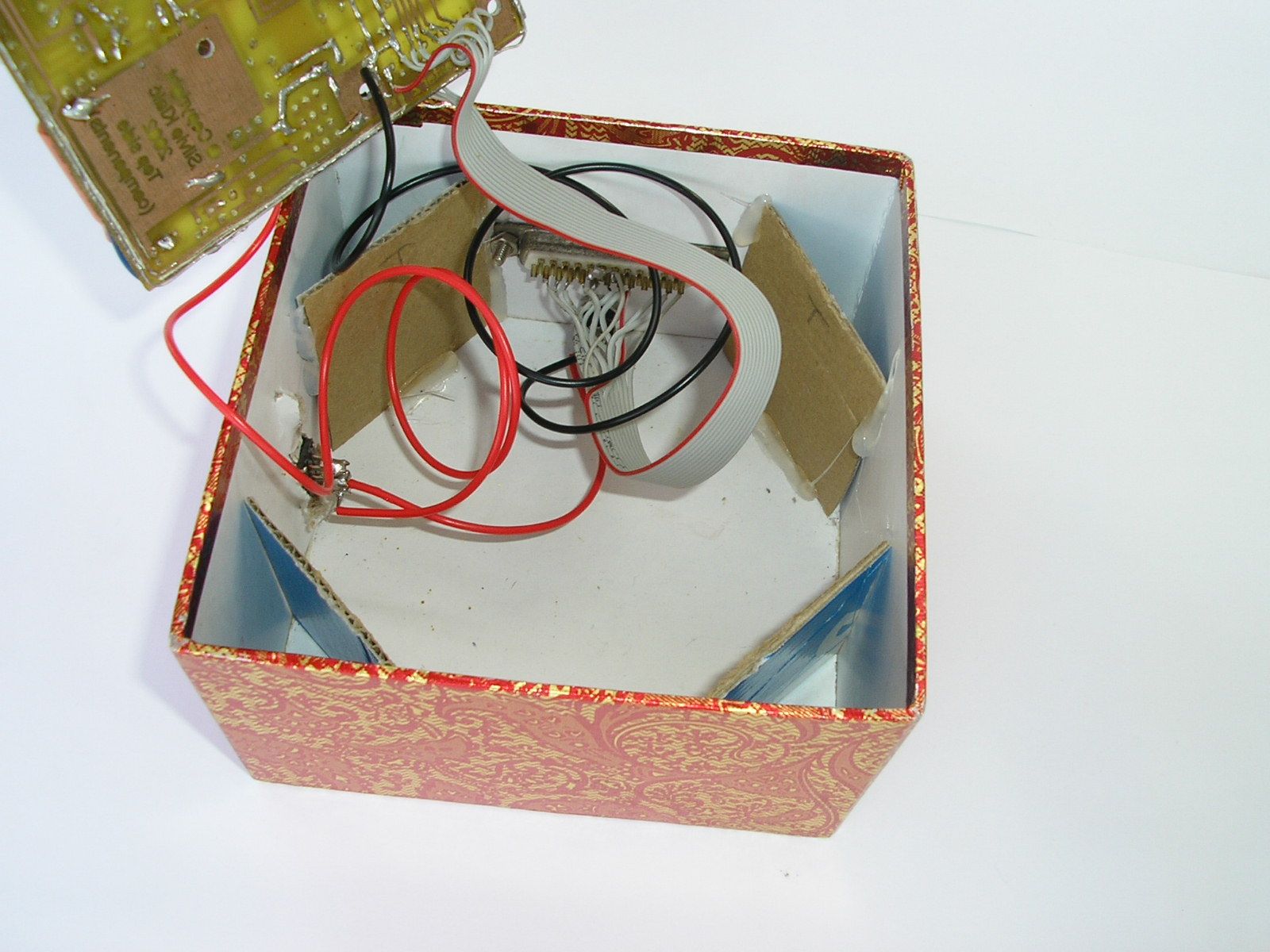
I've found that "gift boxes" made out of thick cardboard are very convenient for making into cases for odd electronics projects (you'll see a lot more of them here if I ever get around to writing up my other projects). For this case I decided that I liked how leaving the board of the DSA tester somewhat loose allowed it to be lifted out to get to the port and power wiring underneath. So I cut some pieces of cardboard to the right height that they would sit in the corners of the box and hold the board just below the lid, into which holes were cut for the LEDs, Voltage Regulator, and test socket. The LED holes were tight enough that they hold the board in position (rough handling isn't expected).
For the cable to the PC's Parallel Port, the project's author used a custom-made cable so that a smaller DB-15 connector could be mounted on the PCB. As with my build of the DSA tester, I chose to mount the connector on the case instead of the PCB, which meant that I could use a standard Male DB-25 connector and a regular Male-Female Parallel Port cable. Similarly, the power socket and switch are mounted on the case under the circuit board.
None so far, I tend to default to the DSA tester when I make new tests because it has a test editor and more tests already available. However I do have that test format converter project at the back of my mind. One day, one day...
Until that day, and as with the DSA tester, I would be very happy to put any tests that you've written for this tester here for download with full attribution. Send me an Email!