|
Scopetrex Build Notes/Modifications |

Sorry, I couldn't get a good photo of the oscilloscope picture
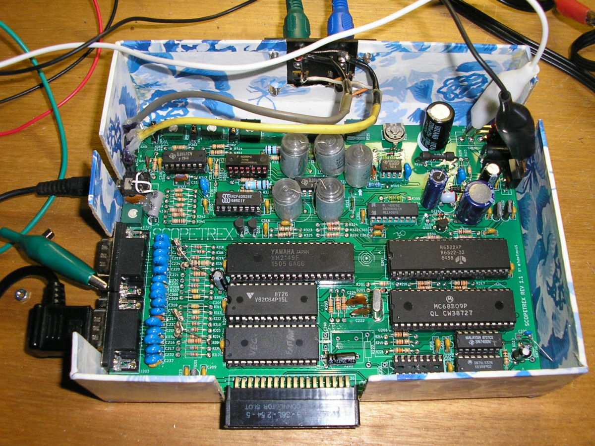
The Scopetrex is a project by Tube Time for recreating the original Vectrex circuit on a modern PCB using components that are more easily available today. It is designed for displaying on a cathode-ray oscilloscope with an X-Y mode, or other vector display. Construction details, PCB layout, and schematics are at GitHub.
This page breifly documents some modifications and observations from my own build. I'm also selling PCBs for the main board, along with sets of all the components which aren't available from Mouser, at my OmberTech online store.
In some cases I attempted to stick to the original parts list from the Vectrex service manual in preference to changes made in the new design. Many choices were based on what parts I had available, so they're just documented to show that the substitutions are an option.
Substitutions
- The Scopetrex parts list doesn't specify the type of capacitors to use for C304-C306 (sample-and-hold circuit capacitors) and C312+C313 (integration capacitors), though the photo shows that the author used regular multilayer ceramic caps. The Vectrex service manual shows that polystyrene capacitors were used for these parts, and their improved leakage characteristics should be an advantage. The Vectrex also used 10nF caps for all of these, however the scopetrex makes C304-C306 4700pF. I reverted them back to all 10nF polystyrene capacitors, though as only 600V rated caps were in my stocks they are noticably large.
- Some resistor values had changed around the DAC circuitry. R305, R303, and R301 were changed from the original 2.7K 1% to 2.49K 1%, and R303 from 3.6K 1% to 2.61K 1%. The original values were used, both because I was using the original cap values and because the original value resistors were more easily available locally.
- BC559 transistors were used instead of 2N3906 for Q301 and Q302, because I already had them.
- The original parts list notes that the LF347 (U303) and LF353 (U304) Op-Amp chips can be substituted with TL084 and TL082 Op-Amps respectively, I only had the latter models in my stocks, so used them.
- I had some old V62C64P15L RAM chips, so used one of those instead of the specified AS6C62256 for U204. The extra capacity of the specified chip isn't used in the scopetrex circuit anyway. Both chips are the same size, and the only modification required was to cut the track connecting pin 26 to GND, and connect it to 5V instead, as it is an active-High Chip Select input on the V62C64 instead of an (unused) address input on the AS6C62256.
- I had some 27C256 EPROMs, and the specified AT28C64B EEPROM was out of stock anyway, so that was used for U201. For this, pin one had to go to 5V instead of GND, and pin 27 had to go to GND instead of 5V. This switch-around was again achieved by cutting tracks and wiring the pin to a nearby point. I drilled out the pin 1 hole so as to remove the connections to GND which would be difficult to cut.
- I used an original R6522 chip rather than the modern CMOS version specified. No PCB modification was required.
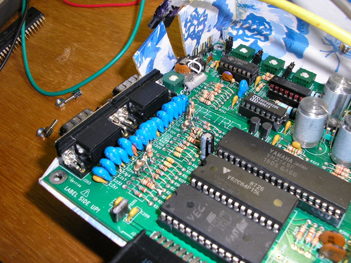
- The PCB accomodates using the original AY3-8912 sound chip, the similar AY3-8910, or the compatible YM2149F. The latter was cheapest to buy, so I used one of them and the sound seems quite equivalent. However the chip also reads the controller button inputs and I discovered that, while an original controller works fine, my VecAdapt adapters had an odd effect where buttons (except button 4) would linger reading as pressed for about a second after being released. It seems that the YM2149F has extremely weak pull-ups on its button inputs compared to the AY3-8912, which affects the timing of the VecAdapt circuit. Button 4 is connected to a 3.3K pull-up resistor, presumably related to its alternative serial I/O function, and wiring six extra 3.3K resistors from R218-R210 and R222-R224 to 5V solved the problem. This is shown on the photo below.
Photos

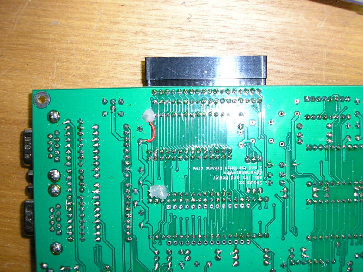
Underside of assembled circuit board showing rewiring of U204 and U201 connections to support V62C64P15L RAM chip and 27C256 EPROM

Additional resistors required for VecAdapt compatibility if a YM2149F sound chip is used
Neither of my X-Y capable oscilloscopes were sensitive enough on their Z-input for blanking to work effectively. One, which specified 40V blanking signal, fails to blank the trace at all. The other almost works with the brightness adjusted just on the threshold of visibility, but the centre-spot is still clearly visible and raster text is barely readable. A buffer circuit which increases the voltage of the Z signal should solve this problem, though as both 'scopes require a positive signal for blanking, this would require an additional voltage regulator on the scopetrex board. For me, the second 'scope works well enough for my purposes anyway. In other respects the display seems good, and equivalent to a Vectrex, besides the obvious reduced size.
Content Copyright Kevin Koster 2022