Computer Nerd Kev |
Home|About|Projects|Links |
Projects > Sig. Trig. |
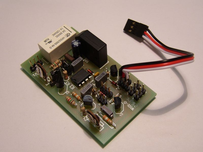
R/C Servo Signal Trigger |
The main inspiration for setting up this site, this little creation allows you to effectively add functions to your existing R/C set-up for models, robots, model robots, etc.
I'm selling kits on Tindie along with a few assembled ones and some bare PCBs. You can also now order from my new online store, OmberTech.
The following is taken from the instructions so you can get some idea of what I'm on about. For those who can be bothered to find out how it works (or want to see if they can work out what all the parts do just from looking at the schematic (you're better than me if you can work out what R4 does with a quick look)), click on the above link to the Circuit Description. You get the schematic thrown in as well.
The Signal Trigger allows the triggering of an additional on-off function remotely using an existing R/C receiving system suitable for driving Servos, and a transmitter with a minor modification.
The Signal Trigger connects to the signal used by one Servo (which may remain in operation using the same control channel) and detects the depression of a button or switch installed on the transmitter. This allows an additional on-off function to be triggered remotely without sacrificing a full R/C channel to the job. A 2 Amp relay is used to for the switching action, and may be connected similarly to a normal switch.
This circuit completely eliminates the need for a physical servo operating a microswitch, and in the process allows functions to be triggered using the R/C system without the loss of any channels.
The Signal Trigger has three basic modes, selected by jumper locations described below:
R/C Receivers control servos and ESCs using a Pulse Width Modulated (or PWM) control signal. This means that they tell them how far to turn or how fast to go by varying the duration of time that an electronic pulse is sent (the Pulse Width). These pulses are commonly sent at a frequency of 50Hz, though sometimes 40Hz is also used, as such every 20ms (1s/50Hz = 0.02s) a positive pulse is sent. With the control stick and trim at their middle position on the transmitter, this pulse should be approximately 1ms in length, when you move the control stick or trim on a transmitter this pulse length will change. From the perspective of a servo, the instruction to move to a position between 90° and 180° will be given as a pulse between 1ms and 2ms in length, while the instruction to move between 90° and 0° will be given with a pulse between 1ms and about 0.25ms in length.
In analogue transmitters the trim function is provided by a mechanical bias on the control stick's rotation of the potentiometer inside the control stick assembly. As the potentiometer turns to produce a signal read by the transmitter to determine the position of the control stick, when trim is set below maximum, a full movement of the control stick does not result in full rotation of the potentiometer and therfore a signal less than that for maximum rotation (about 2ms in length) is sent to a servo by the receiver. As a result, where the trim is set below maximum rotation, there is some "dead space" in the range of signals that are sent which is never used during normal operation.
The Signal Trigger takes advantage of this "dead space". By disconnecting the Ground connection to the potentiometer (or the Supply Voltage connection, if the channel is set as reversed on the transmitter), the transmitter circuitry determines that the potentiometer is at its maximum position (max. trim and max. control stick) and therefore tells the receiver to send a full 2ms pulse to the servo. The Signal Trigger reacts to this long pulse and may optionally disconnect the signal connection to the servo to prevent it from reacting itself (the delay imposed by the relay may allow some servo movement, depending on the load on the servo). See the Circuit Description for a more detailed look at how the circuit works.
Many digital transmitters do not use a mechanical trim, instead determining the extent of servo movement using software. As a result there is little or no "dead space" at the end range of the potentiometer, is it is read over pretty much its full rotation. As a substitute, a mechanical limit must be installed (as described in the "Transmitter Modification" section of the Instructions), and preferably, the range of travel extended in software to compensate.
The output of the Signal Trigger is through a relay (though the connection to pin one of the relay may also be used as an output with 200mA current capacity, however with relatively large loads, pulses may be present on the output in Non-Latching mode (see Circuit Description)). The provided relay has a maximum switching current of 2A and a maximum voltage of 220VDC. It is a DPDT type, one pole configured to allow switching off the servo signal while to other is provided as three connections for any other use (in place of a switch). If it is desired to use the signal switching pole for another purpose, connections can simply be soldered to the corresponding pins of the relay, however unless the relay is connected off the PCB, the long trace running from its third pin along the bottom side of the board should be cut (this connects it to the servo signal).