|
7400 Series Discrete Logic Word Clock |
Clocks are a problem for me, I keep designing them but I never seem to finish building my designs. I'm not really sure why.
Maybe it's because I limit myself to using only TTL logic, or that my designs usually involve excessively complicated
wiring or mechanics, or I guess maybe it's because I always wear a watch? Well anyway, these are some of the ideas that I've
had over the years, many of which got as far as a completed circuit design and beginning construction:
- Brake Disc Clock
- Discrete Logic Meter Clock
- Randomly Ticking Clock (three designs for this, none built yet)
- Discrete Logic Whiteboard Clock
- VFD Clock (nothing too special about this one)
- Infinity Clock
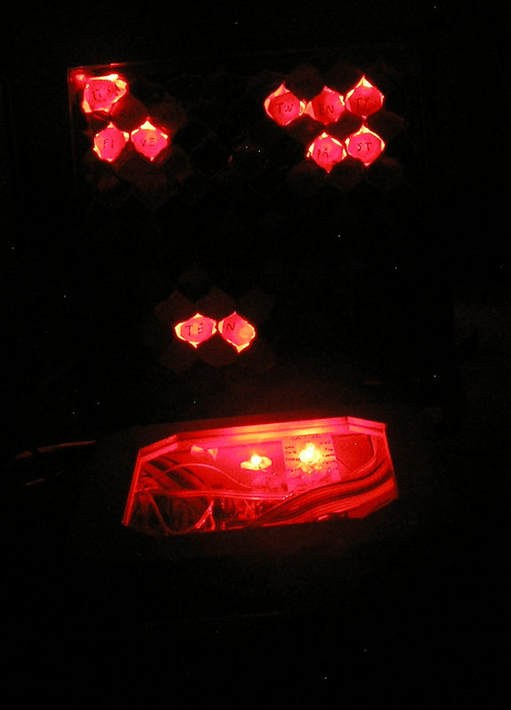
But this time I've finally come through with one, my own microcontroller-less take on "Word Clock" designs, which display
the time in words by lighting up letters in a grid.
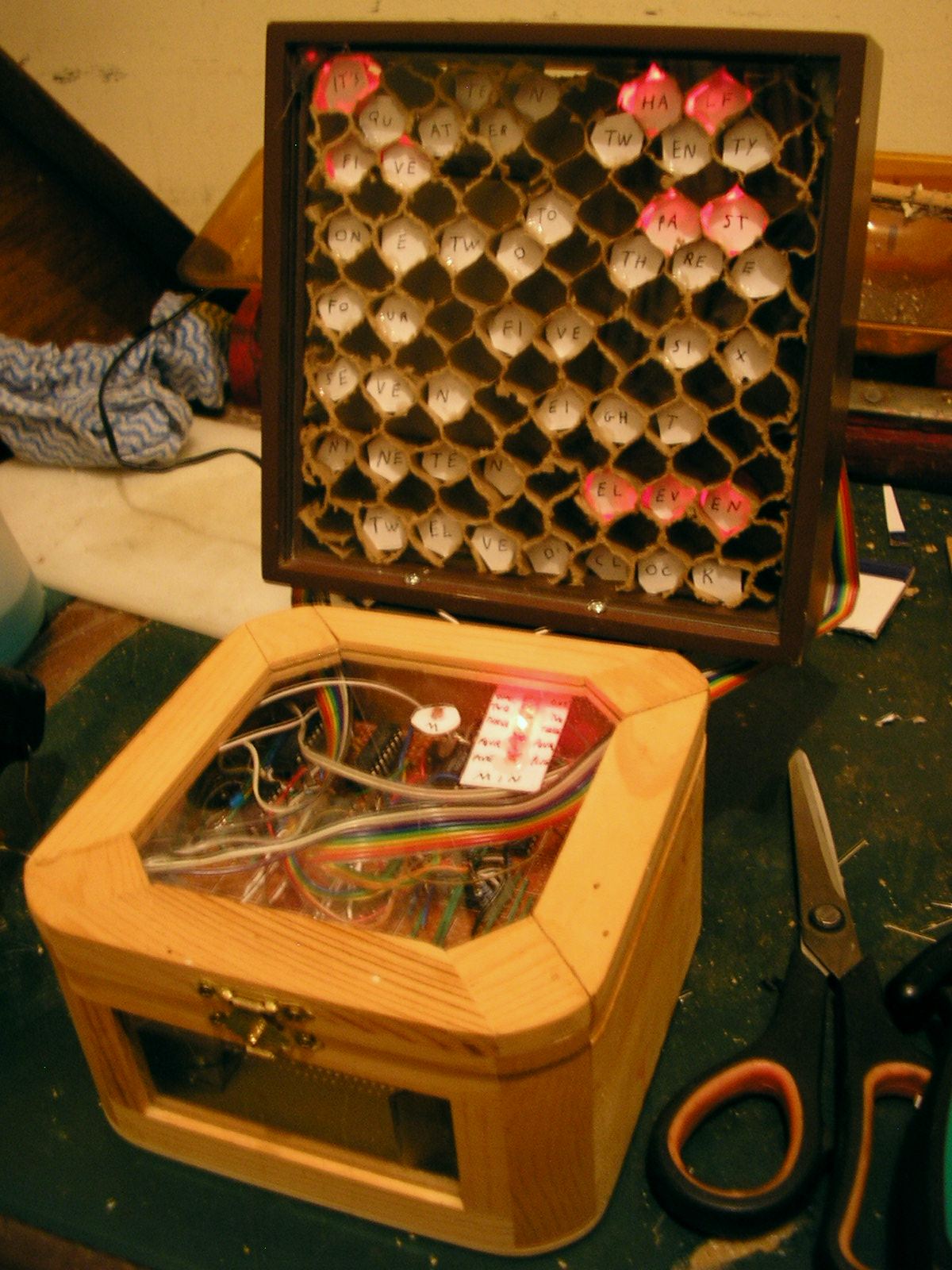
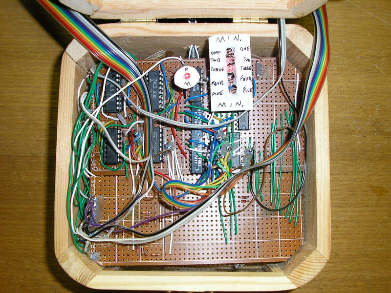
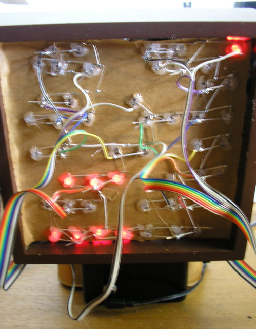
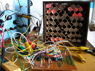
"FIVE" is dimly lit in the left image because I accidentally used a resistor for D12 instead of a diode and
hadn't figured that out yet when the photo was taken.
| Interested in buying a kit for the logic board of this clock? Let me know by
submitting your email address to the notifications list and if there's significant interest then I might put one
together, along with clearer schematics, instructions, and 60Hz mains support. Approximate cost would be $53.00AUD
(USD
CAD
EUR
GBP) plus postage. |
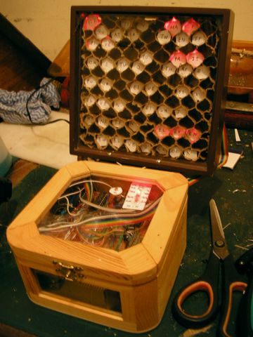
Usually the display for these things is LEDs shining through letter-shaped slits or unshaded areas in a panel placed in
front. I was going to go a similar route, but thought I should have each light in its own compartment within a grid in order
to avoid lighting up surrounding letters. I had some very strong (you can stand on them!) cardboard panels with a fairly
deep honeycombe structure inside. By cutting off one side of it to fit within a second-hand photo frame that I'd picked up
for $2 years earlier, thinking it looked deep enough to fit lots of electronics inside, I had a pre-formed grid. The shapes
of the slightly squashed honeycomb structure looked more interesting than the usual plain modernistic design of other word
clocks. So instead of covering it up, I started cutting out little discs of matte inkjet-printable photo paper, just the right shape so
that they could be jammed in the holes and held in place by friction. To keep them in place for good I first tried dabbing
on superglue, which just made them go stiff and no longer stay in place at all, then resorted to my usual uglier but reliable
hot glue. The text is just written in permanent marker, and reports so far are that nobody else can read my writing, but I'm
putting that down to a lack of effort by the readers.
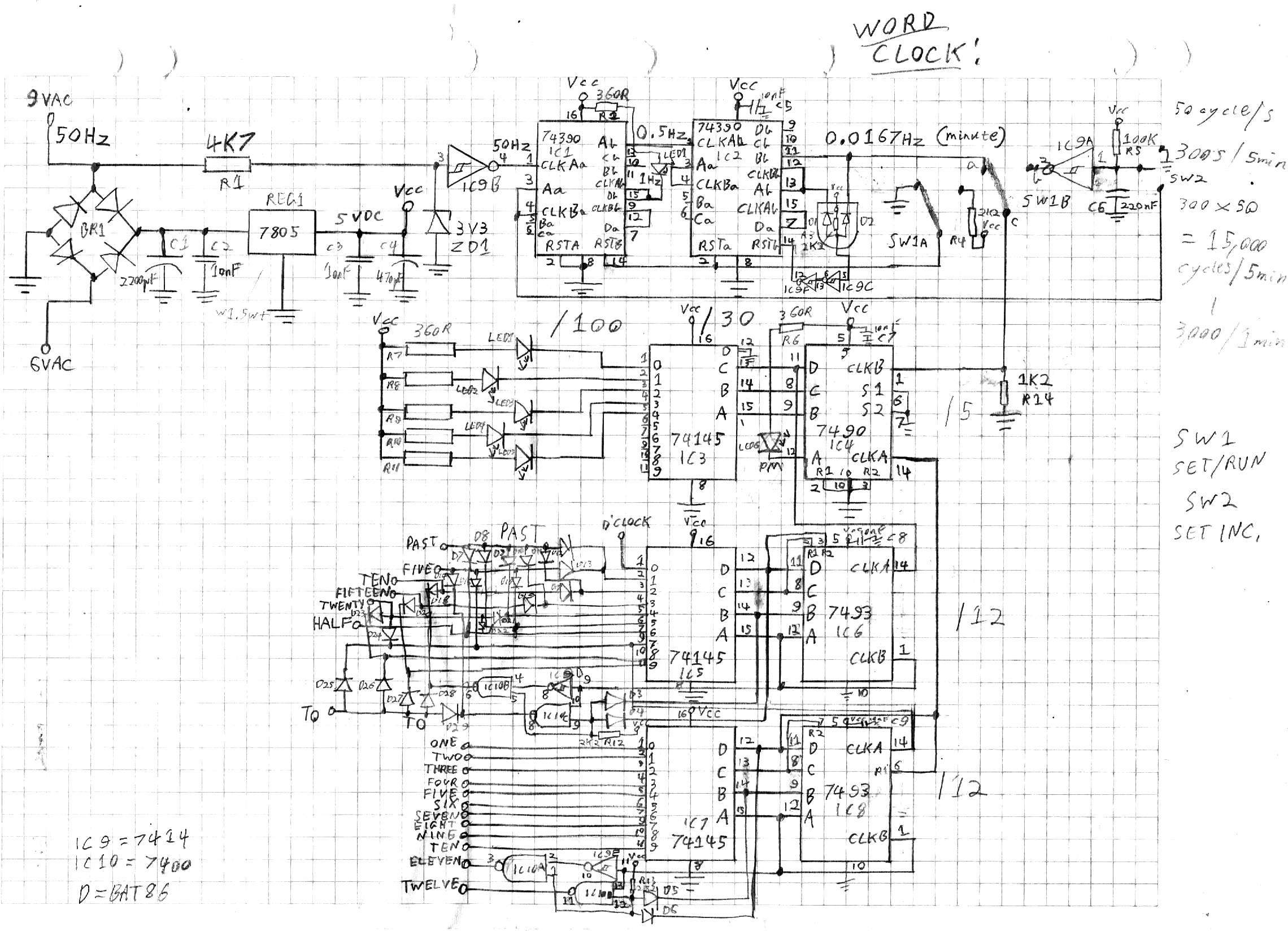
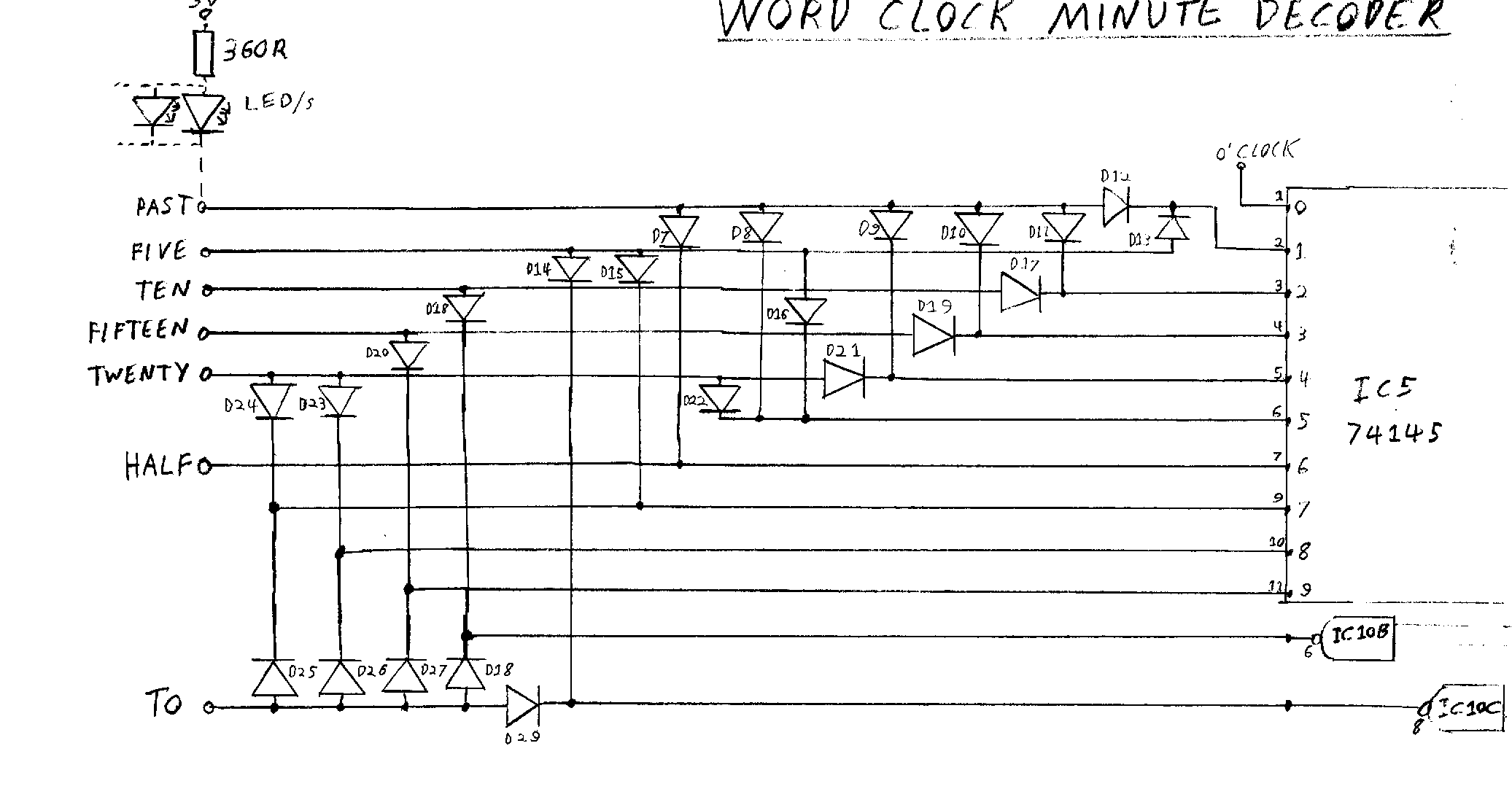
The schematic below shows the circuit design, which uses 74145 binary decoder ICs to convert the binary counter outputs to
individual signals that can light ten LEDs in sequence, with a little bit of extra logic to decode the eleventh and twelfth
states. Understandably, there's no such chip tailored to encoding in the form of the English language, so a diode array is used
to form the middle of phrases such as "IT'S FIVE PAST EIGHT" and "IT'S TWENTY FIVE TO FOUR". This diode array has been
enlarged especially for you in the second image, because admittedly even I could barely make sense of my original squished-up
maze of diodes hanging off the outputs of IC5. Also unlike a conventional clock, the hours count has to advance at the "TWENTY
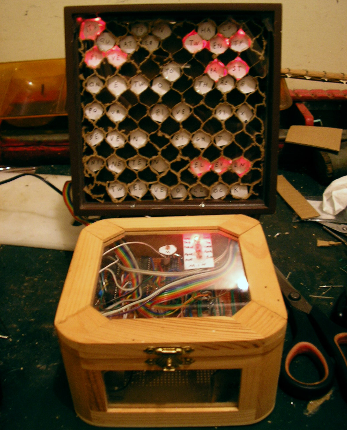
FIVE TO" position, rather than on the hour. The minute and AM/PM LEDs are kept separate above the logic board and can be
seen through the glass in the lid (I decided against including the 1Hz flashing LED shown in the schematic).
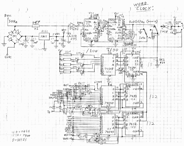
Word Clock schematic. A DPDT latching push-button switch was used for SW1, and a SPDT momentary toggle switch for SW2. Note
that there may be some errors because this was revised after construction. In fact, that should be 9VAC on both ends of BR1
for starters!
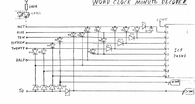
Expanded view of the diode array on the outputs of IC5, which connects with the cathodes of LED rows in the display.
The timebase is taken from the mains frequency, a traditional arrangement for discrete-logic clock designs. IC1 and IC2 are
dual counters with divide-by-two and divide-by-five stages, wired up to divide the 50Hz (in Australia) mains frequency down to a rate of one
pulse per minute. They also supply a higher frequency signal used for skipping forward while setting the clock, where it
allows you to zip up close to the correct time before using the pulse function to jump forwards one minute per button-press.
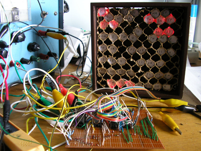
Construction was on veroboard, but the original veroboard layout needed to be modified extensively during construction so I won't bother
presenting it here. My main error was with the initial selection of counter chips for IC6 and IC8. I was looking at a datasheet
which neatly covered the 7490, 7492, and 7493 all in one. The 7490 on one side counts neatly in binary from zero to nine. The
7493 on the other side counts in binary all the way up to 15. The 7492 counts conveniently to eleven, so twelve states just
as is needed in the latter stages of the clock, and in binary too... right up until you get to six when it makes a seemingly
unscheduled jump up to binary-eight and continues on like nothing happened. As a silly person with a few 7492 chips spare who
didn't read all the way through the truth table, it wasn't until I'd finished building the logic board and was scratching my
head at the strange output sequence that I realised this. So various bits of re-wiring were required to enlist some 7493s in
place of those tricky chips, which in turn introduced a whole lot of poor wire connections that lead to various troubles later
on.
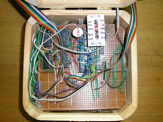
It even includes some old chips made in the dark year of 1974 when 7400 series logic chip inscriptions became hopelessly
confusing (hint: the date code)!
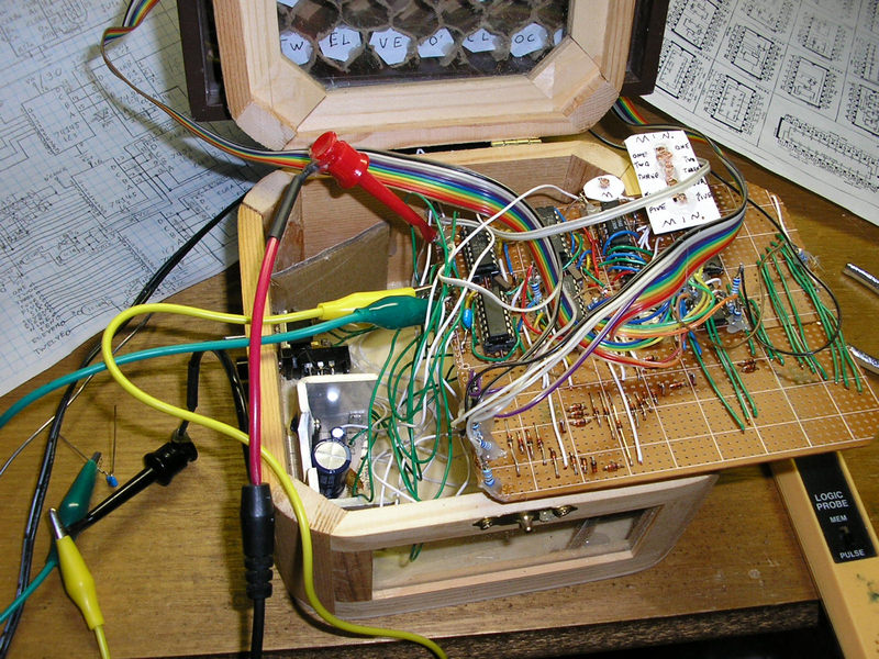
Another mistake seems to have been putting ZD1 on the logic board. ZD1 cuts off the higher part of the AC input fed into
the Schmitt trigger inverter to provide the 50Hz timing signal. The problem I had was that after running for a few minutes,
the clock would suddenly start going at double-speed. It turned out the first stage of IC1 which divides the 50Hz signal
by two was going from outputting a nice 25Hz square wave to a bunch of short pulses LOW (or sometimes inverted, and HIGH) on every input
cycle, so not dividing the 50Hz signal at all. Though my old oscilloscope wasn't fast enough to see it, there must have been
a spike on the ground connection to IC1 (located near ZD1) which upset it, occouring just as it as trying to change states. Eventually I found
that increading R1 from 1K to 4K7 worked to avoid this, presumably just by reducing the voltage of the spikes, but it's not
a good solution and I'd recommend other constructors keep R1 and ZD1 separate from the logic board, with a separate wire
connecting ZD1 to the power supply's GND.

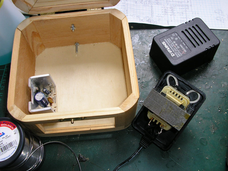
As the mains waveform is used for the 50Hz frequency reference, an AC supply is required. I pulled apart an old transformer plug-pack
and removed the rectifier/regulator board, putting it inside the clock where both the AC and DC lines can be accessed, but with
the 240V mains input to the transformer still kept safely over in the plug pack.
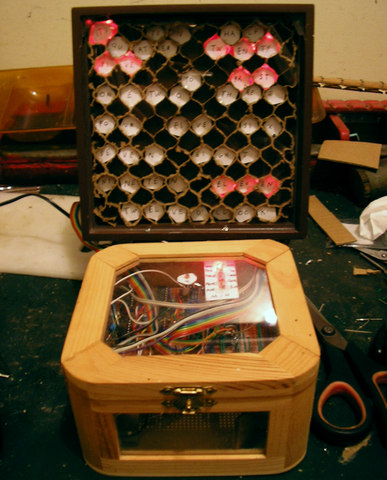
Like the photo frame used for the display, the case for the logic board and regulator board was some sort of wooden gift
box that I'd picked up second-hand somewhere. I like that the glass top allows me to show off the discrete logic chips, though
it also exposes my hurried wiring of the logic board to criticism. The stand for the display is one of the cases I use for my
VecAdapt controller adapters which arrived cracked, and it was bolted on somewhat imperfectly (I'd run out of my allotted
time twice by that point and was trying to put everything together quickly in an afternoon) at an angle for convenient viewing.

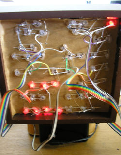
The LEDs were high-brightness red ones, so that they would be bright without drawing significant current. Granted if I
were being true to the 7400 series logic era of the 1970s, I probably should have used small filament light bulbs. But better
not to be wasting power by running light bulbs all the time, and also you wouldn't want them getting hot around all that
cardboard. Plus I already had lots of ultrabright red LEDs, and not many tiny light bulbs. The current-limiting resistors
were stuck with one end in the logic board, and the other soldered directly to the rainbow cables running over to the back
of the display where they attached to the wacky rows of joined-together LED leads.

Now to get back to all of my other clock projects, one day...
Content Copyright Kevin Koster 2021