Mechanical_Description
- Edit
- Recent Changes
- Advanced Search
- All Pages
- Administration
- Index
Mechanical_Description 
In this page we'll document various options for the cartridge case, how to mount the Pi, and how to attach peripherals such as USB and HDMI.
Cartridge Case
Low-Pressure Moulded Case
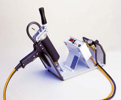
This technique uses a Low-Pressure moulding machine to encase the cartridge board. It requires metal moulds to be manufactured to accept the cartridge boards and produce a case that is compatible with the Vectrex cartridge receptacle.
Kevin Koster is currently experimenting with DIY metal casting techniques for producing the moulds. So far tests are simply to establish the easiest technique for producing aluminium castings from ABS plastic models.
The results of the first experiment, using a technique based on the "lost-foam" method (but with ABS plastic 3D prints with very sparse infill) show promise, but modifications to the process are clearly required to improve metal penetration into the plastic part. Weakening the entry surface on plastic models, adjusting the application/type of refractory coating, and increasing the head pressure of the molten aluminium, may be solutions to the problems observed so far.
Second test was much more successful, pouring the aluminium into a pipe sitting on top of the sand (and "investment") in order to increase the pressure. Also, removing the bottom wall of the 3D prints and replacing it with polystyrene hot-glued on also worked very well. Next stage is to try making the actual moulds for the cartridge case.
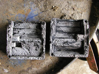
UPDATE: The case moulds have been successfully cast in aluminium. One wall at the cartridge connector end of the mould was too thin for the aluminium to penetrate into, but this might be alright as an insert had to be inserted here one way or another in order to form the cavity around the edge connector. The mating surfaces are uneven, which is mainly due to issues with the original 3D print, which required hot glue to fill some voids in the surface before applying the refractory coating.
These surfaces will have to be machined level, and also the aforementioned insert pieces manufactured, before moulding cases can be attempted. A general tidy-up of other surfaces, probably with a Dremel, would probably be a good idea as well.
UPDATE: Moulding of cases using the first mould castings proved difficult, this was presumed to be due to insufficient room for plastic to flow around the encapsulated PiTrex circuit board inside.
A redesigned mould with a thicker mid-section was cast, though with more casting issues than before. Even less success was had with this for reasons apparantly unrelated to the mould itself. Problems may be due to substituting the correct moulding plastic for hot glue during testing, or an incorrect nossle on the moulding machine. Due to the expense of the minimum order quantity of the correct plastic, manufacture of another nossle for the moulding machine is being attempted. This is presenting some difficulties.
3D Printed Case
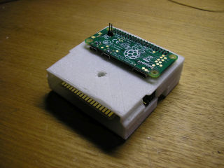
Users with access to a 3D printer may produce their own case to suit the PiTrex Discrete cartridge, using the 3D models
 designed by Kevin Koster based on his 3D printable cartridge case designs on Thingiverse
  .
.3D Model STLs:
For no DC Socket or Jumper Pins
A size M3 (3mm) or 1/8" nut and 22mm long bolt are required to secure the cartridge case together.
Besides eliminating the burden of constructing the cases for sale with the cartridges, a further advantage of this approach is to reduce the thickness of the package to be posted. International economy postage from Australia using "letter" services can be less than a fifth the cost of parcel services, but only applies to items less than 20mm thick. This saving may be sufficient incentive for many users to 3D print their own case. These services are without tracking, however. Note that this "Economy Airmail" service was suspended due to Coronavirus by the time of release anyway, so it's not currently a consideration.
Note that the DC socket will probably not be able to be included if the parcel is to be under 20mm thick after wrapping in appropriate padding material.
Modified Reproduction Vectrex Cases
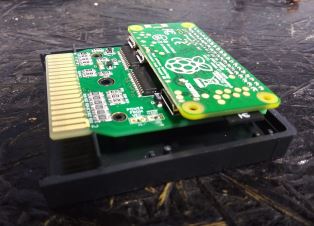
While requiring custom tooling to produce the required holes in existing reproduction cases on a larger scale, this option is again possible for users having purchased a bare cartridge PCB, as suggested for use with the 3D printable case design. The PiTrex Discrete PCB is designed to fit within the standard Vectrex cartridge case and use the same mounting hole sizes/positions. Using a Dremel, Graham Toal has successfully modified a reproduction case with the required hole for the GPIO header to attach with the Raspberry Pi Zero above. Some users may choose to make additional holes for access to the pin jumpers, and the DC socket. The latter will require more work to accommodate as it requires a hole in the bottom and the side of the case.
Graham Toal has been active in assessing methods of modifying cartridge cases that would be suitable for small-scale production. Success has been achieved using a Dremel stand and a template pattern. Also, a CNC device has been used to cut the hole completely automatically.
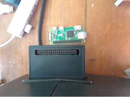
More recently, 'Arcade' Jason Kopp changed the header on the PiTrex so that the Pi Zero could be fitted entirely inside a standard cartridge! The zero does have to be soldered in, which may be awkward in some circumstances:
Mounting the Pi Zero on the PiTrex
The PiTrex Discrete PCB was designed for the Raspberry Pi Board to be mounted horizontally above the cartridge, in such a way as to minimise the total area occupied by the unit and reduce the risk of accidental knocks bending/breaking GPIO pins and their solder connections.
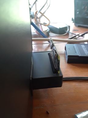
A problem with this is access to the HDMI and USB connectiors, when are then facing the Vectrex case, allowing not enough room to connect standard cables.
Graham Toal suggests using right-angle header connectors to allow the Pi to be mounted vertically. This does increase the potential for bending the GPIO header from accidental tugs on connected cables, due to the increased leverage.
You can get 40-wide connectors from this eBay vendor
 and break them in half.
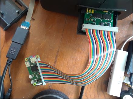
Using a parallel cable as an extender
Rather than squeeze cables into the gap, you can widen the gap by using a male<->female parallel cable with the connectors on the same side. This would also allow the use of a larger raspberry pi if desired (though note the increased power consumption - a system like that would almost certainly require the use of external power)
These two sources look like suitable cables: eBay
 Amazon
- beware of similar IDE cables which generally have a missing center pin.
Right-Angle Cables
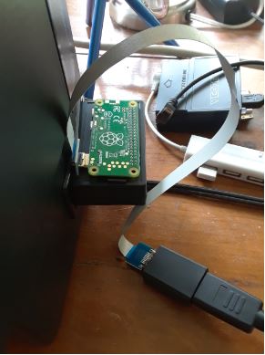
The gap between the Raspberry Pi HDMI and USB connectors may be sufficient to allow use of an "FFC" type right-angle cable, as available from a limited number of Chinese retailers (the manufacturer has not yet been determined). These cables may also adapt from the Pi0's Mini HDMI and Micro USB sockets, to the full-size connectors that suit most peripherals.
A right-angle FFC HDMI cable
 , and a similar USB cable
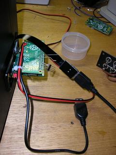
  , have been successfully tested, and found to fit within the gap:
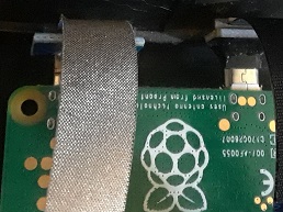
Here are both an HDMI and a USB cable in place. We noticed that the USB male connector sticks out a mm or two farther than needed and so the Pitrex cartridge cannot be fully and tightly inserted. It works but you do need to exercise more care that the cartridge is not accidentally knocked out:
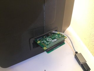
Brandon Yates reported on the developer's mailing list that these
 "Cable Creation" branded right-angle Micro USB adapter cables can fit, as pictured below. These are likely to be cheaper and easier than the FFC cables.
USB gadget adapters
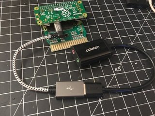
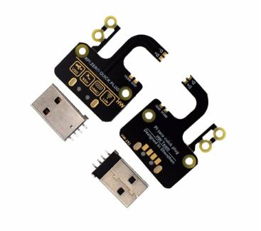
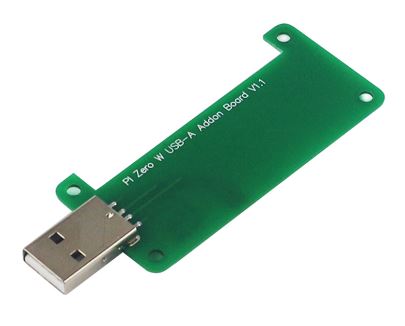
Test pads on the Raspberry Pi Zero boards allow connection to all of the USB signals. These can be soldered to the wires of a cable with a USB socket at the other end, or circuit boards are available cheaply on Ebay that allow a full-size USB socket to be mounted on the bottom of the Pi0 board, pointing in away from the Vectrex. One of these options requires users to solder connections to the Pi0 board if it is not supplied with the PiTrex cartridge and the other one is a press-fit board that uses "pogo plugs" instead of soldering. Unfortunately these add-ons convert the Pi Zero into a USB gadget that can be plugged in to another computer (with a suitable M<->F extender cable) but the male USB A plug precludes plugging USB devices into the Pi Zero with these adapters. However, where these may be useful could be in plugging the Pi Zero into a Windows PC or Mac as the equivalent of a flash drive, to load new programs on to the SD card. (Although if your PC has an SD reader, that would not be necessary)


